
Member bar bending device

A technology for bending devices and rods, which is applied in the field of rod bending devices and can solve problems such as large springback

Inactive Publication Date: 2017-06-13
GUANGDONG UNIV OF TECH
View PDF9 Cites 0 Cited by
  • Summary
  • Abstract
  • Description
  • Claims
  • Application Information

AI Technical Summary

Problems solved by technology

[0004] In view of this, the object of the present invention is to provide a rod bending device, which can effectively solve the problem of relatively large rebound after bending

Method used


Image

  • Member bar bending device

Examples


Embodiment Construction

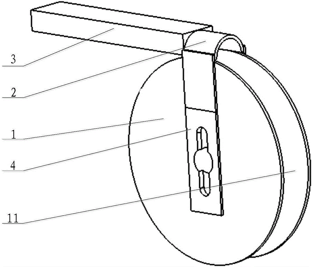
[0021] The embodiment of the invention discloses a bar bending device to effectively solve the problem of relatively large springback after the bar is bent.

[0022] The following will clearly and completely describe the technical solutions in the embodiments of the present invention with reference to the accompanying drawings in the embodiments of the present invention. Obviously, the described embodiments are only some, not all, embodiments of the present invention. Based on the embodiments of the present invention, all other embodiments obtained by persons of ordinary skill in the art without making creative efforts belong to the protection scope of the present invention.

[0023] see figure 1 , figure 1 Schematic diagram of the structure of the rod bending device provided by the embodiment of the present invention.

[0024] In a specific embodiment, this embodiment provides a rod bending device, which is used to bend the predetermined part of the rod into an arc shape to...


PUM


Abstract

The invention discloses a member bar bending device which comprises an engine base, and an elastic mold with an annular curved surface, wherein the elastic mold is arranged on the engine base and can elastically deform along the radius direction of the annular curved surface. In the member bar bending device, the material of the elastic mold is changed into an elastic material, so that a member bar is fuller in deformation under the condition of the curved elastic mold, the stress and strain of internal and external sides are larger, and the spring back angle is reduced. Therefore, by adopting the member bar bending device, the problem that the spring back amount of the member bar after being curved is relatively large can be effectively solved.

Description

technical field [0001] The invention relates to the technical field of tool machinery, and more specifically, relates to a bar bending device. Background technique [0002] The use of the elbow prevents the components from interfering with each other, which can reduce the weight of the overall structure and save raw materials. The elbow also has the function of absorbing impact energy and is widely used in industrial production. However, after the bending of the pipe is completed and the mold is removed, the rebound recovery effect of the pipe reduces the final bending angle and increases the bending radius, thereby reducing the geometric and shape accuracy of the pipe and making the connection between the elbow and other parts Decreased performance and compactness of the overall structure. [0003] To sum up, how to effectively solve the problem of relatively large springback after bending of the bar is an urgent problem for those skilled in the art. Contents of the inve...

Claims


Application Information

Patent Timeline
IPC IPC(8): B21D7/024
CPCB21D7/024
Inventor 肖小亭刘志峰陈名涛何建春
Owner GUANGDONG UNIV OF TECH
Learn More