Impact absorbing member

Inactive Publication Date: 2009-01-29
TOKAI RUBBER IND LTD
View PDF10 Cites 18 Cited by
  • Summary
  • Abstract
  • Description
  • Claims
  • Application Information

AI Technical Summary

Benefits of technology

[0028]As described above, the present invention can provide an impact abso

Problems solved by technology

However, distribution of a load of the impact absorbing member (speaking in detail, reaction force applied from an impact absorbing member to an impact applying object when the impact applying object collide with the impact absorbing member) described in these documents is not uniform throughout the entire length

Method used


Image

  • Impact absorbing member
  • Impact absorbing member
  • Impact absorbing member

Examples


first embodiment

[Arrangement of Impact Absorbing Member]

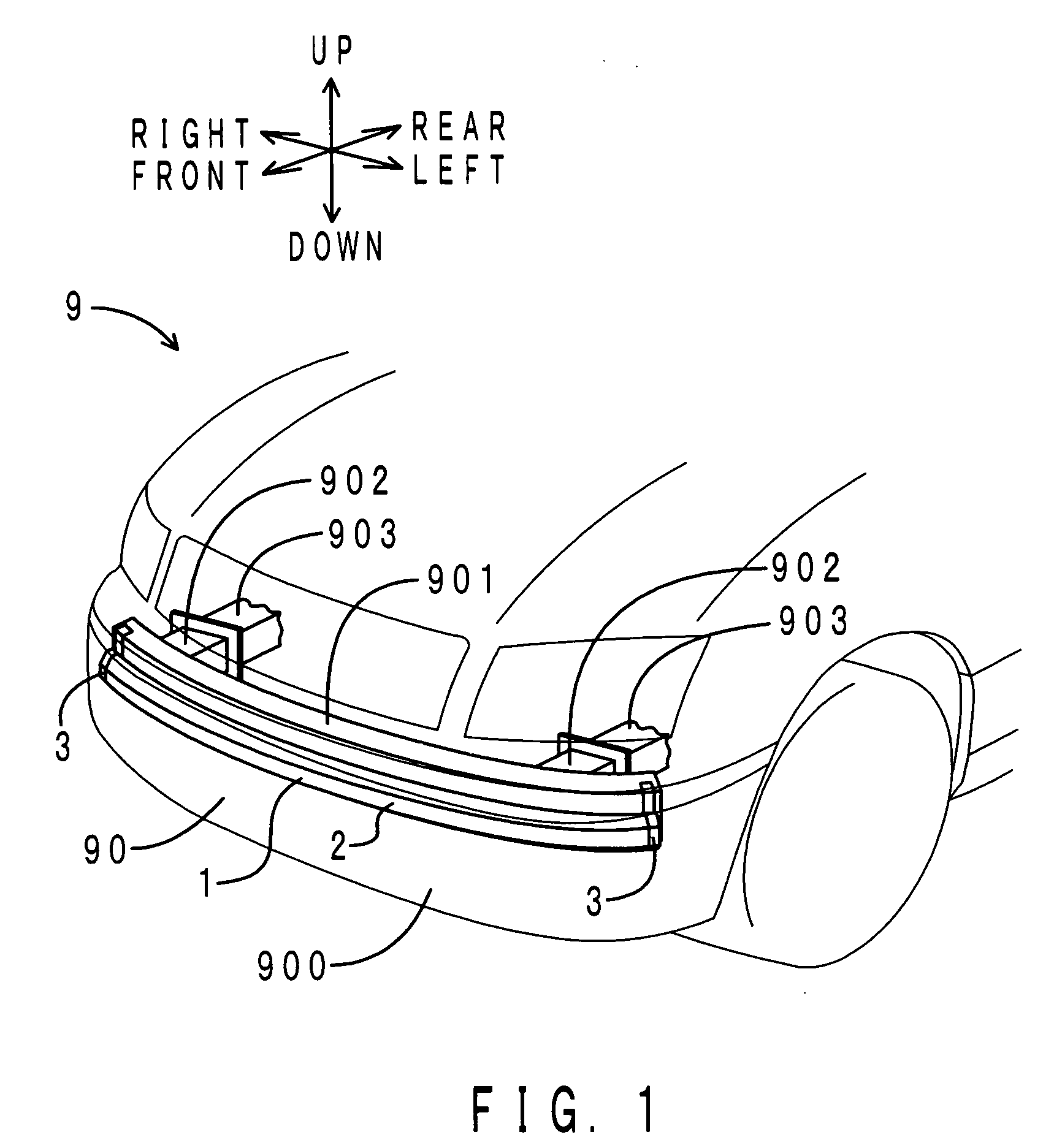
[0048]First, the arrangement of the impact absorbing member of this embodiment will be described. FIG. 1 shows a transparent perspective view of the vicinity of the front bumper of a vehicle in which the impact absorbing member of this embodiment is disposed. In the meantime, in FIG. 1-FIG. 10, the directions (right / left) are defined as a vehicle as viewed from its rear to the front.

[0049]As shown in FIG. 1, a front bumper 90 of a vehicle 9 includes a bumper fascia 900, a bumper beam 901 and a crush box 902. The impact absorbing member 1 is disposed in front of the bumper beam 901. In the meantime, the bumper beam 901 is included in the abutting member of the present invention.

[0050]The bumper beam 901 is made of aluminum alloy. The bumper beam 901 is of a long quadrangular pipe. The bumper beam 901 is extended in the vehicle width direction (right and left direction).

[0051]The crush box 902 is made of aluminum alloy. The crush box 902 is of a...

second embodiment

[0077]The impact absorbing member of this embodiment is different from the impact absorbing member of the first embodiment in that the impact absorbing member is disposed on the roof side rail portion, not on the bumper beam. Further, the second embodiment is different from the first embodiment in that the mounting member is installed on the roof side rail portion by means of a clip, not by pawl engagement. Therefore, only different points will be described here.

[0078]FIG. 6 shows a perspective view of the interior of a vehicle compartment in which the impact absorbing member of this embodiment is disposed. Note that components corresponding to those in FIG. 1 are denoted by the same reference symbols. As shown in FIG. 6, a roof lining 8 made of resin is disposed on the ceiling of a vehicle compartment. Two columns of the impact absorbing members 1 (expressed by hatching in FIG. 6) are accommodated on each of right and left edges of the interior of the roof lining 8 such that they r...

third embodiment

[0083]The impact absorbing member of this embodiment is different from the impact absorbing member of the first embodiment in that the mounting member is installed to the bumper beam by means of bolts, not by pawl engagement. Therefore, only different points will be described here.

[0084]FIG. 9 shows a partial sectional view of the impact absorbing member of this embodiment as viewed from the left side in the vicinity of the left end portion of the impact absorbing member of this embodiment. Note that components corresponding to those in FIG. 5 are denoted by the same reference symbols. A pair of the mounting members 3 are disposed on both right and left end portions of the impact absorbing body 2. FIG. 9 shows the mounting member 3 at the left end portion of the impact absorbing body 2. The mounting member at the right end portion of the impact absorbing body 2 has the same structure. Therefore, only the mounting member 3 at the left end portion will be described here and descriptio...


PUM


Abstract

An object of the present invention is to provide an impact absorbing member capable of reinforcing a desired reinforcement object portion. The impact absorbing member includes a long impact absorbing body which absorbs energy at the time of a collision by being deformed itself and a mounting member which is disposed at a reinforcement object portion of the impact absorbing body so that it is deformed along deformation of the reinforcement object portion at the time of the collision and mounted to a mounting object member. When the reinforcement object portion is deformed at the time of the collision, the mounting member is deformed along deformation of the reinforcement object portion. Due to that deformation, the mounting member can reinforce the reinforcement object portion.

Description

INCORPORATION BY REFERENCE[0001]The disclosure of Japanese Patent Application No. 2007-196324 filed on Jul. 27, 2007 including the specification, drawings and abstract is incorporated herein by reference in its entirety.BACKGROUND OF THE INVENTION[0002]1. Field of the Invention[0003]The present invention relates to an impact absorbing member for protecting a passenger in a vehicle and a pedestrian by absorbing an impact at the time of a collision.[0004]2. Description of the Related Art[0005]For example, Japanese Unexamined Patent Application Publication No. 2006-62635 and Japanese Unexamined Patent Application Publication No. 2007-118931 have disclosed long impact absorbing members to be installed on a bumper beam or a roof side inner panel of a vehicle. The impact absorbing member absorbs energy at the time of a collision by being deformed itself. Thus, if any impact absorbing member is disposed on a bumper beam, it can mitigate an impact applied to a pedestrian (hereinafter, refer...

Claims


Application Information

Patent Timeline
IPC IPC(8): B60R27/00B60R19/18B60R21/02B60R21/34
CPCB60R2019/186B60R19/18
Inventor MURAYAMA, MASARUSUZUKI, JUNICHIRO
Owner TOKAI RUBBER IND LTD
Why Eureka
Try Eureka