Quick Connector

a quick connector and connector technology, applied in the direction of hose connections, couplings, pipe elements, etc., can solve the problem of lowering the sealing performance of the quick connector at an early stag

Active Publication Date: 2007-10-04
SUMITOMO RIKO CO LTD
View PDF11 Cites 20 Cited by
  • Summary
  • Abstract
  • Description
  • Claims
  • Application Information

AI Technical Summary

Benefits of technology

[0013]In order to achieve a foregoing object, there is provided a novel quick connector in accordance with the present invention. The quick connector comprises a tubular connector housing that is provided with a tube connecting portion (a portion to be connected to a resin tube or a rubber hose) on one longitudinal end thereof and a pipe retainer portion on the other longitudinal end thereof, and retainer means that is arranged in the pipe retainer portion. The retainer means snap-engages with an annular engaging projection that is formed on an insertion end portion of a pipe that is inserted in the connector housing and thereby locks the pipe with respect to the connector housing. The retainer means has a pair of retainers that are disposed diametrically opposite sides of a passage way of the annular engaging projection, and release arms that are provided on the retainers, respectively. Each of the retainers has a fixing end portion integrally connected to and supported by the pipe retainer portion, and a free end (a free end portion or a portion including a free end portion) including an engaging portion for snap-engaging with the annular engaging projection. The retainers are resiliently deformable in such manner that the free ends (free end portions or portions including free end portions) spread out or spread apart taking the fixing end portions as fulcrums or with the fixing end portions as center of rotation by pressing the pair of release arms radially inwardly from outside or from radially outside. The free ends (free end portions or portions including free end portions) of the retainers engage with the pipe retainer portion of the connector housing radially outwardly, when being deformed in the other longitudinal direction (in the other axial direction, or in a direction opposite to a pipe insertion direction). Each of the release arms has a cross-s

Problems solved by technology

By the way, when vibration of an engine or a motor vehicle body is transmitted to the quick connector via the pipe and the quick connector quivers or vibrates tremulously with respect to the pipe, an

Method used


Image

  • Quick Connector
  • Quick Connector
  • Quick Connector

Examples


Embodiment Construction

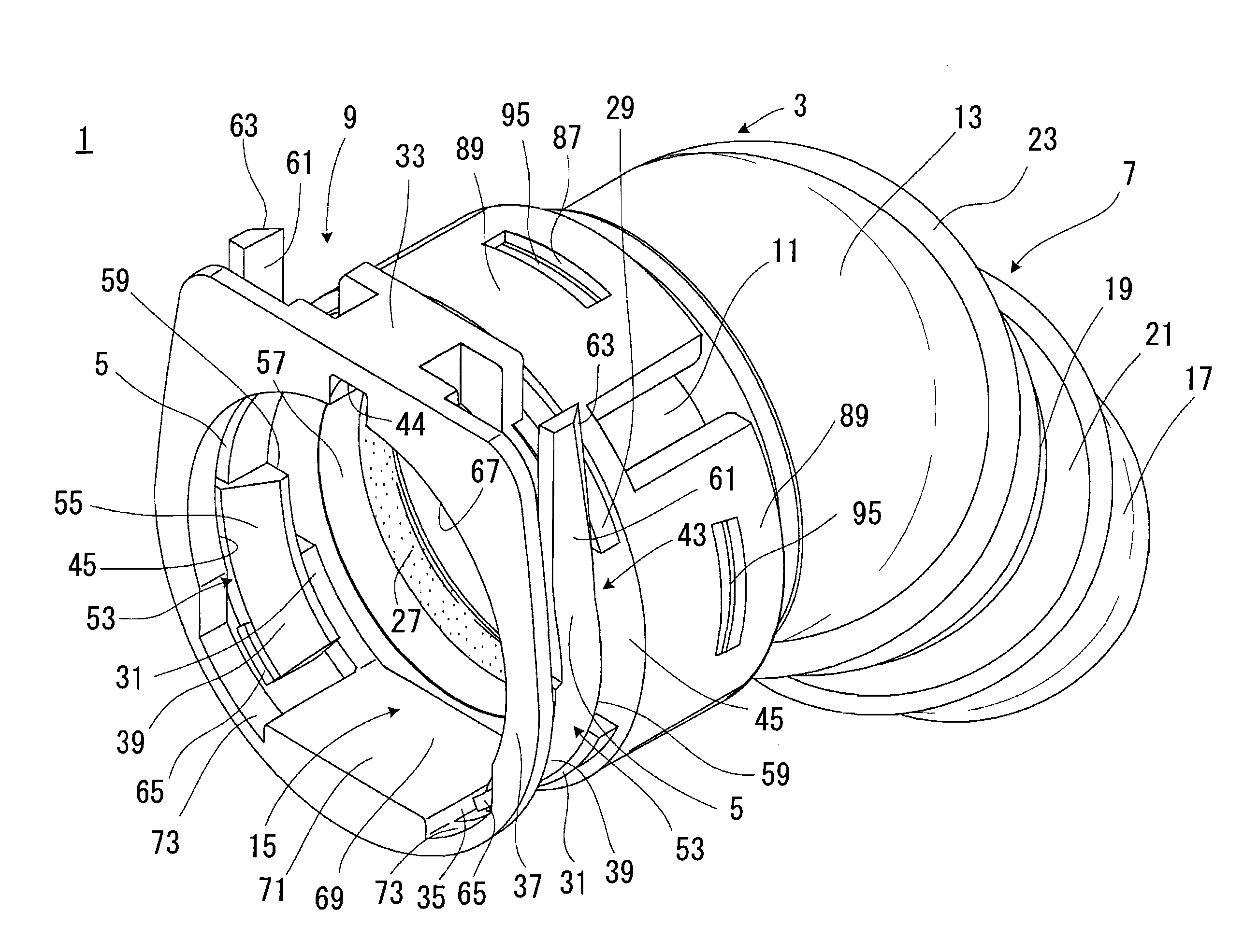
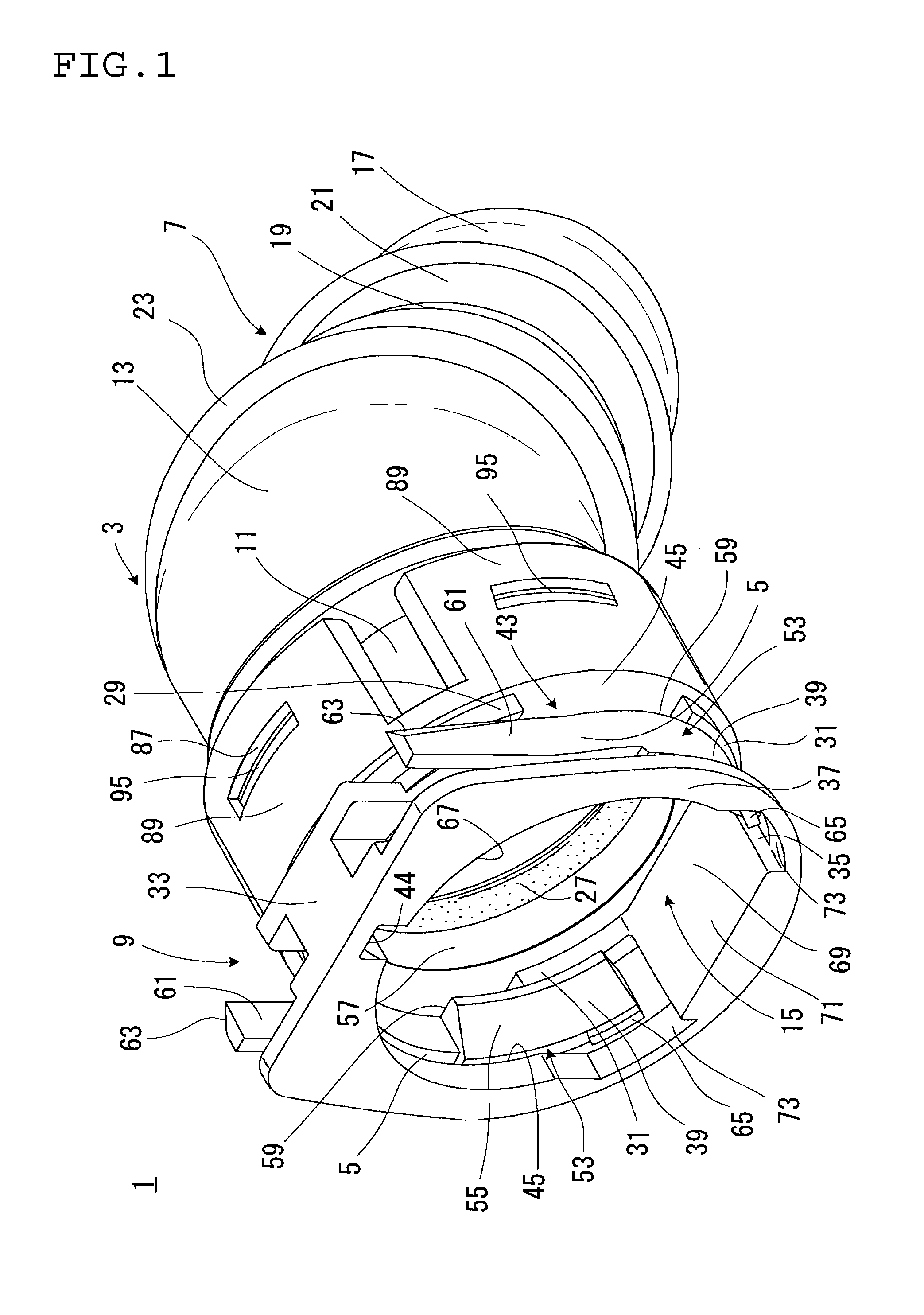
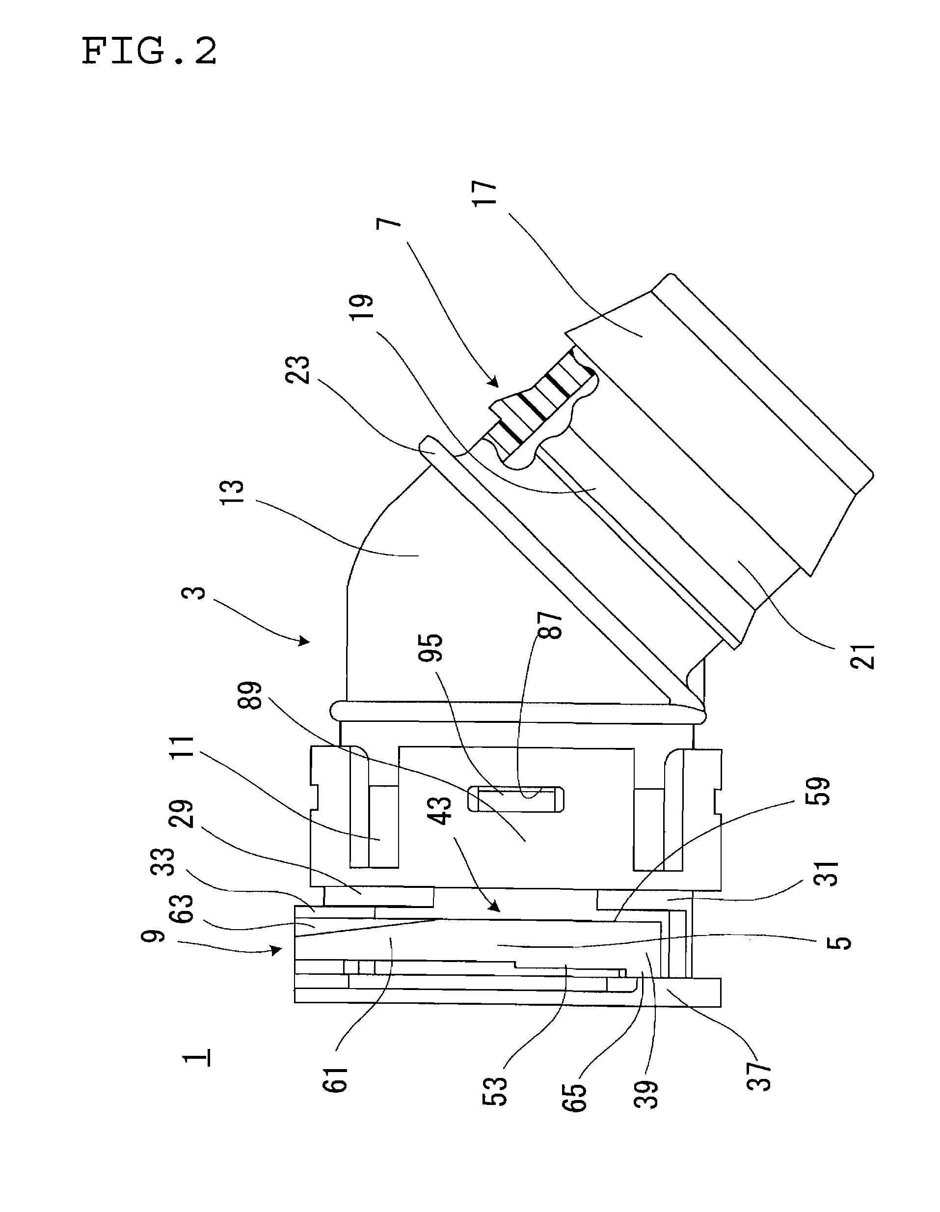
[0035]With reference to FIGS. 1 to 4, a configuration of a quick connector 1 according to the present invention will be explained.

[0036]The quick connector 1 of FIG. 1 is adapted for connection in piping for engine coolant system or gasoline fuel system for a motor vehicle. The quick connector 1 comprises a tubular connector housing 3 and a pair of retainers 5, 5. The connector housing 3 and the retainer 5 are formed from glass-fiber reinforced polyamide (PA / GF) and integral with each other. The connector housing 3 has a cylindrical resin tube connecting portion or tube connecting portion (herein after referred to as tube connecting portion) 7 on one longitudinal end (one end along a longitudinal direction, one axial end), and a pipe retainer portion 9 on the other longitudinal end (the other end along the longitudinal direction, the other axial end). The connector housing 3 further has a pipe support portion 11 and a curved portion 13 between the tube connecting portion 7 and the p...


PUM


Abstract

Retainer means has a pair of retainers that are disposed diametrically opposite sides of a passage way of an annular engaging projection of a pipe, and release arms that are provided on the retainers, respectively. Each of the retainers has a fixing end portion integrally connected to and supported by a pipe retainer portion, and a free end including an engaging portion for snap-engaging with the annular engaging projection. Each of the release arms has a cross-sectional shape for allowing a pressure on the release arm in the other longitudinal direction, when being pressed radially inwardly from outside.

Description

BACKGROUND OF THE INVENTION[0001]1. Field of the Invention[0002]The present invention relates to a quick connector, for example, to be adapted for assembly in piping of an engine cooling system or a gasoline fuel system in a motor vehicle.[0003]2. Description of the Related Art[0004]In a piping of a coolant system or gasoline fuel system in a motor vehicle, a quick connector is used for connecting a pipe and a mating member such as a rubber hose or a resin tube. Such quick connector is configured to snap-engage with the pipe, and, for example, has a tube connecting portion on one longitudinal or axial end thereof. A rubber hose or a resin tube is fitted on the tube connecting portion, and an insertion end portion of the pipe is relatively inserted in the quick connector through an opening of the other longitudinal or axial end of the quick connector until the pipe is snap-engaged with the quick connector. Thereby the quick connector and the pipe are connected each other with simple ...

Claims


Application Information

Patent Timeline
IPC IPC(8): F16L37/12
CPCF16L37/0985
Inventor MATSUNO, KEIJIMIYAJIMA, ATSUO
Owner SUMITOMO RIKO CO LTD
Why Eureka
Try Eureka