Waste removal method for dry toilets

a technology for dry toilets and waste, which is applied in the field of dry toilet waste removal methods, can solve the problems of reducing the sealing ability of pipes, and reducing the ability of dry toilets to be able to be used

Inactive Publication Date: 2000-08-15
HAWKINS ROBERT D +1
View PDF6 Cites 19 Cited by
  • Summary
  • Abstract
  • Description
  • Claims
  • Application Information

AI Technical Summary

Benefits of technology

The inability of dry toilet waste to flow through pipes can be overcome by the present invention which provides a means by which waste from a dry, film-lined toilet can be processed so as to be readily transmitted through pipes to remote locations without the use of water. This is accomplished by apparatus which compresses the liner material and the solid waste from each flush into a wad which expands when inserted into the pipe. This expanded wad can be pushed along the pipe by the next wad and in turn by subsequent wads that are inserted in the pipe behind it. If the expanded wad conforms well to the sides of the pipe it will form a seal allowing the wads to be pushed through the pipe by air pressure. To form an effective air seal and be transmissible through pipe by air pressure the wad must have elasticity so that it can hold its shape and maintain light contact against the walls of the pipe. This elasticity results from the mechanical properties of the thin liner material which surrounds the solid waste and which when crumpled forms the bulk of the wad. For example, a rubber material would have too much elasticity and would unravel whereas metal foil would have too little elasticity and would not expand. A material such as high density polyethylene film has been found to be sufficiently deformable to retain the wad shape and has enough residual elastic expansion to effect an air seal.

Problems solved by technology

A wad containing any significant amount of free liquid waste could collapse from the pressure of the liquid and lose its ability to seal the pipe.

Method used


Image

  • Waste removal method for dry toilets
  • Waste removal method for dry toilets

Examples


Embodiment Construction

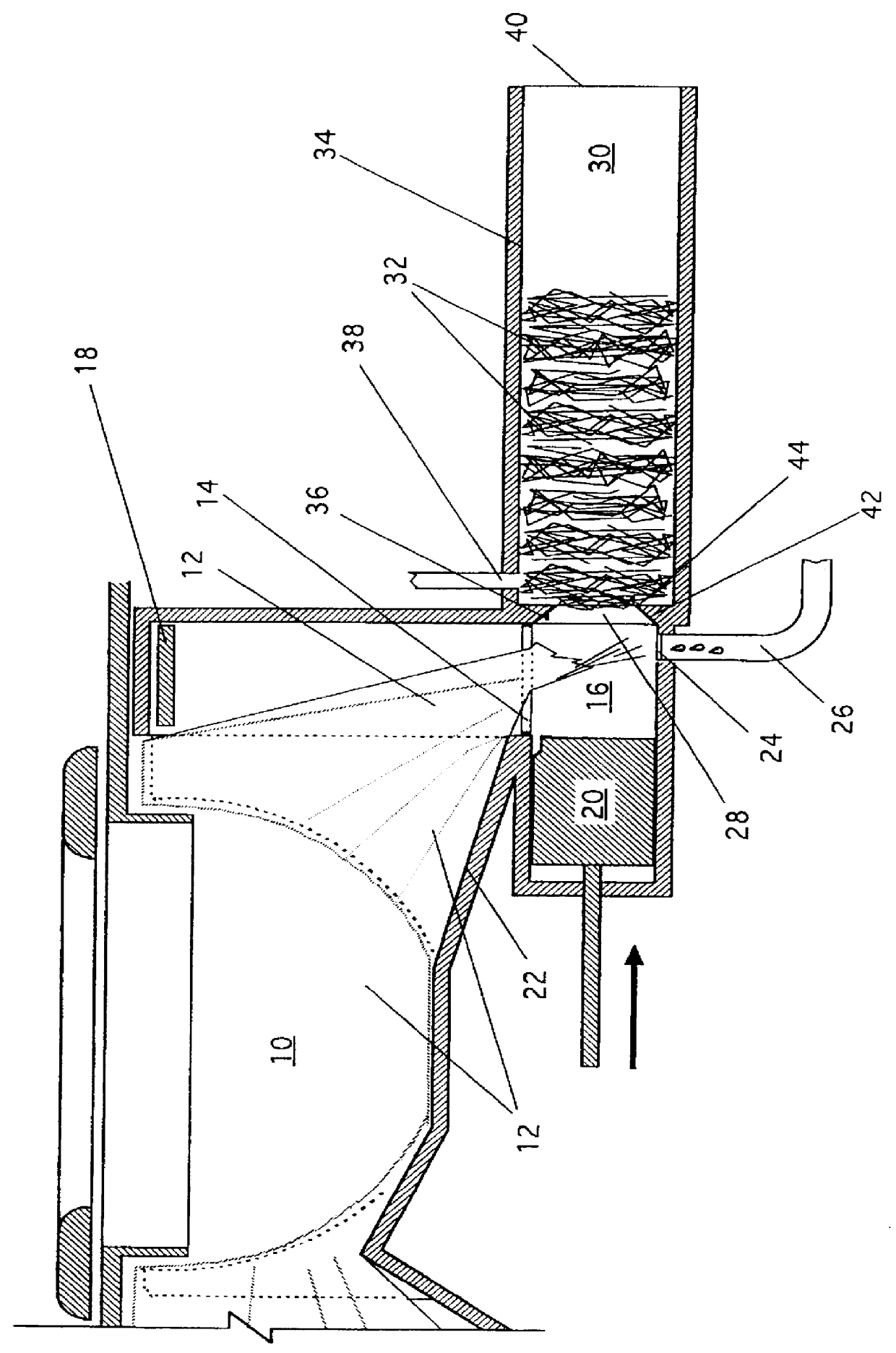
A system for the transmission of waste from a dry toilet shown in FIG. 1 has a toilet bowl 10 with bowl lining sheet 12 which when the toilet is flushed is conveyed from the toilet bowl 10 over an opening 14 in the topside of a piston chamber 16 and released so as to drop into the piston chamber 16. At the start of the flushing cycle a cover plate 18 lifts upward to clear the opening 14 while at the same time the piston 20 retracts to clear the piston chamber 16 for the receipt of soiled liner sheet 12 containing solid waste. The retraction of the piston 20 releases the end of the liner sheet 12, which was pinched between the piston 20 and the topside of the piston chamber 16, thus allowing the liquid waste which has collected by gravity flow in the sloped portion 22 of the toilet bowl 10 to flow out of the open end of the liner sheet 12 and into the bottom of the piston chamber 16 and from there through the filter screen 24 and into the liquid waste drain 26.

When the soiled portion...


PUM


Abstract

PCT No. PCT/US97/16787 Sec. 371 Date Mar. 26, 1999 Sec. 102(e) Date Mar. 26, 1999 PCT Filed Sep. 22, 1997 PCT Pub. No. WO98/14106 PCT Pub. Date Apr. 9, 1998A system for the removal of waste from dry toilet bowls (10) and other containers adapted to have a disposable liner sheet (12) comprising an apparatus (16, 18, 20, 36) for forming elastic wads (32) from lengths of liner sheet (12) containing waste and for inserting the wads through a port (28) into a pipe (34), and an arrangement (38) for introducing air pressure into the pipe near the port to propel the wads along the pipe toward the exit (40).

Description

This invention relates to a method of waste removal to be used with dry toilets with disposable bowl lining material.Toilets which cannot be connected to sewer mains or sewage treatment equipment usually have storage tanks which hold the accumulated waste until such time as it is convenient to pump the waste into a tanker truck for transport to another location where sewage processing is available. This is a common procedure for mobile toilets as for example toilets installed in commercial airliners. Airliner toilets flush by using recirculated chemically treated waste water or by using a small amount of fresh water assisted by the pull of a vacuum. The waste is either stored in tanks beneath each toilet or in remote tanks which hold the waste from several toilets. These tanks can be accessed through connections in the service panels underneath the plane. When the plane is serviced the waste water is drained or pumped into a tanker truck connected at the service panels.The weight of...

Claims


Application Information

Patent Timeline
Patent Type & Authority Patents(United States)
IPC IPC(8): A47K11/02A47K11/00
CPCA47K11/02Y10S4/19Y02A50/30
Inventor HAWKINS, ROBERT D.HAWKINS, JAMES A.
Owner HAWKINS ROBERT D
Why Eureka
Try Eureka