
Method for treatment of ischaemic tissue

a tissue and ischaemic technology, applied in the field of ischaemic cardiac tissue, can solve the problems of reducing tissue function, reducing tissue flow to the tissue, and reducing tissue function, so as to maintain tissue function, stimulate and/or restore the function of those cells, and reduce damage

Inactive Publication Date: 2007-03-15
MCLACHLAN CRAIG
View PDF17 Cites 18 Cited by
  • Summary
  • Abstract
  • Description
  • Claims
  • Application Information

AI Technical Summary

Benefits of technology

[0012] The inventor has found that the structure of the sponge-like element promotes tissue growth and angiogenesis throughout and beyond the element, and that irritation or injury to the surrounding tissue is not necessary to promote tissue growth and angiogenesis throughout and beyond the element. Thus, a particular advantage of the invention is that as the sponge-like element complies with the movement of the tissue, it does not cause chronic irritation, which may lead to excessive fibrosis or scar tissue formation. Accordingly, the method of the invention is improved for treatment of ischaemic tissue because according to the method, fibrosis is at least reduced.
[0013] Further, as the element is structured to comply with the movement of the tissue, there is limited, if any, damage to cells which surround the element when the element is arranged in the tissue. This is important for maintaining the functional integrity of the tissue. Further, it is believed that the arrangement of the element in the tissue may stimulate and / or restore the function of those cells which surround the element. Thus, further advantages of the method of the invention include reduction of damage and restoration of function, to those cells which underpin the function of the tissue.
[0014] Still further, the inventor has found that tissue growth and angiogenesis can be promoted throughout and beyond the sponge-like element without seeding the element with cells, or impregnating the element with growth or angiogenesis promoting factors or other factors, etc.
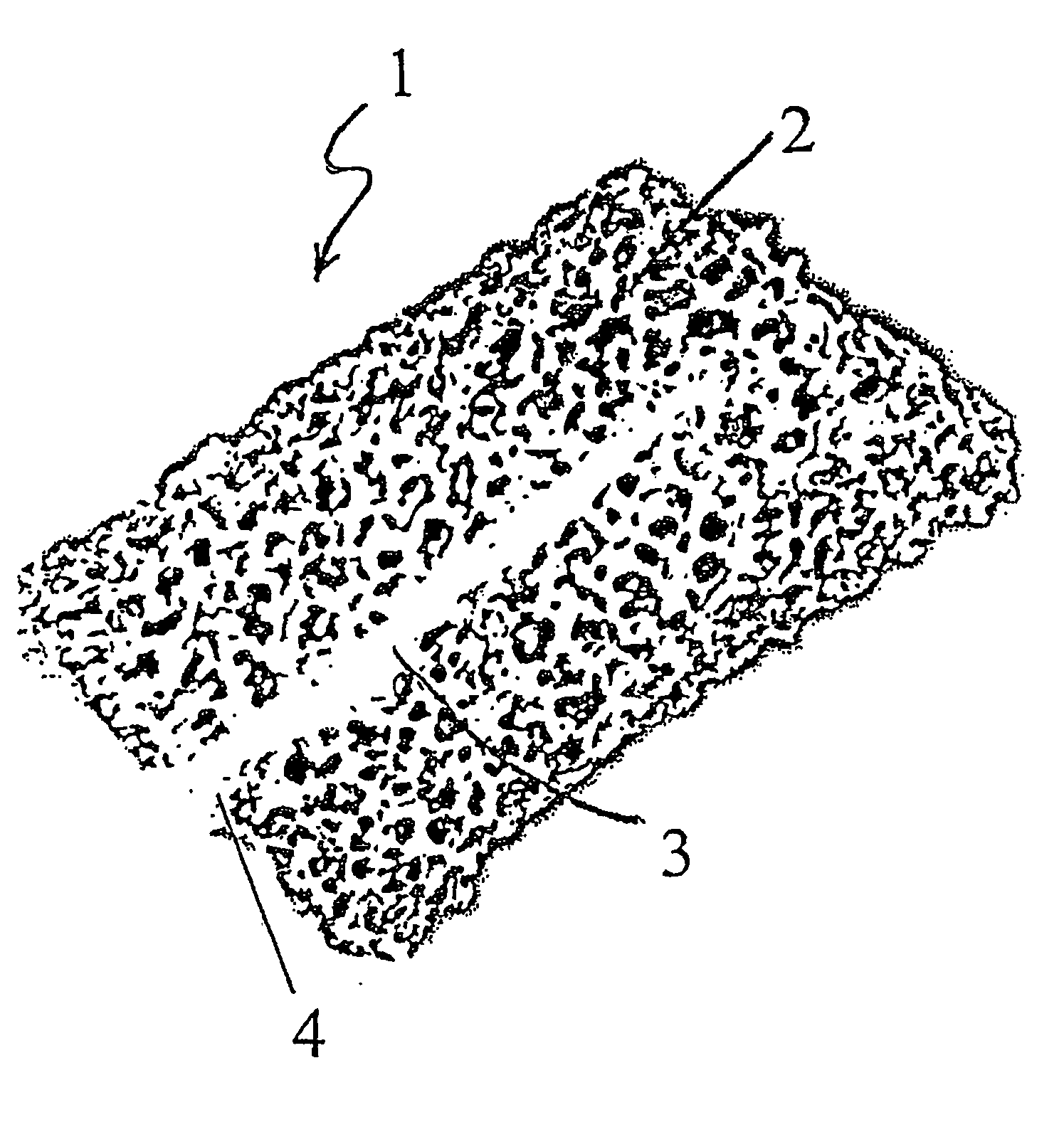
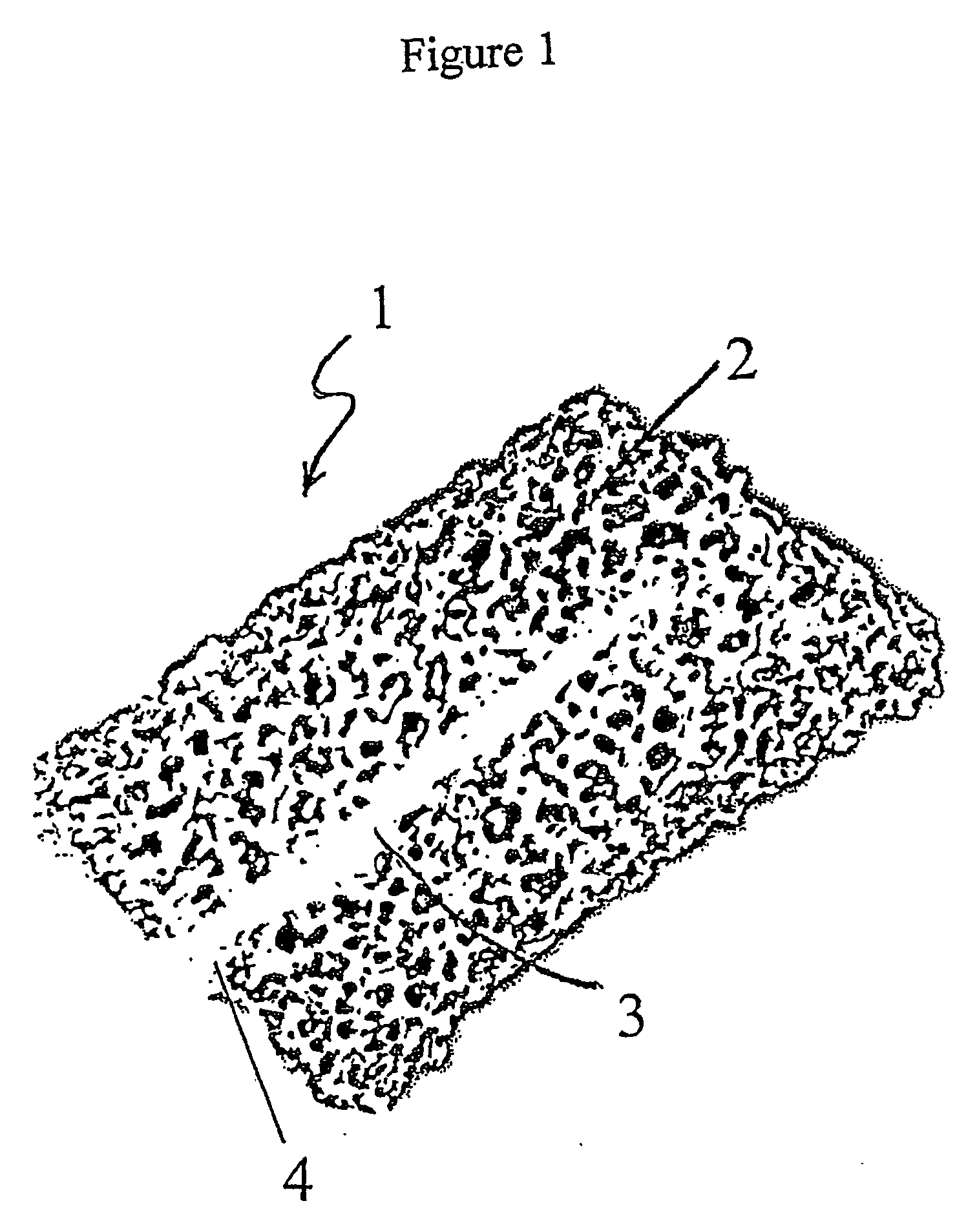
[0015] The sponge-like element is sufficiently deformable to comply with the movement of the tissue in which it is located. Typically, the element is resilient to the extent that it can be compressed by the surrounding tissue during a tissue contraction such as systole, and it can expand to fill the wound when the tissue is expanding, such as in diastole. The sponge-like element comprises a plurality of interconnected cells or pores. The pore size of the sponge-like element will be optimal for blood vessel growth in and through the element. Typically, the size of the pores of the element are less than 250 microns in diameter. Preferably, the size of the pores range from 50 to 200 microns in diameter.
[0016] The void content of the porous structure, or in other words, the proportion of the volume of the element that is pore space, is typically between 50% and 90% of the total volume of the element. This void content is optimal for tissue growth and angiogenesis throughout and beyond the element. Preferably, the void content is between 70% and 90% of the total volume of the element.
[0017] The sponge-like element may be of any shape provided it can be fitted to the wound. For example, the element may be a block, or may comprise a recess for insertion of cells or compounds into the element for direct passage of fluid. As a further example, the element may be recessed along a substantial portion of the length of the element to create a channel for passage of blood into the channel.

Problems solved by technology

Consequently, circumstances which lead to depletion or loss of vascularisation may lead to reduction in blood flow to the tissue and reduced tissue function.
Diseases that result from a reduction of blood flow and as a result, reduced tissue function, constitute a significant health problem in industrialised countries.
The loss of blood flow to regions of the heart muscle may result in reduction of heart muscle function, or damage to the heart muscle as is the case in diseases such as angina (stable or unstable), pre-infarction angina, myocardial infarction, heart failure or in patients with cardiac pacing.
Once in the tissue, the device expands to the second configuration resulting in injury and / or irritation to the surrounding tissue.
Once inserted, the implant expands to a second configuration that causes injury to the surrounding tissue and thereby provokes an injury response that results in angiogenesis.
However, the approach decribed in U.S. Pat. No. 6,458,092 leads to excess fibrosis and scar tissue formation, damage to surrounding tissue and loss of tissue integrity.

Method used


Image

  • Method for treatment of ischaemic tissue
  • Method for treatment of ischaemic tissue
  • Method for treatment of ischaemic tissue

Examples


Embodiment Construction

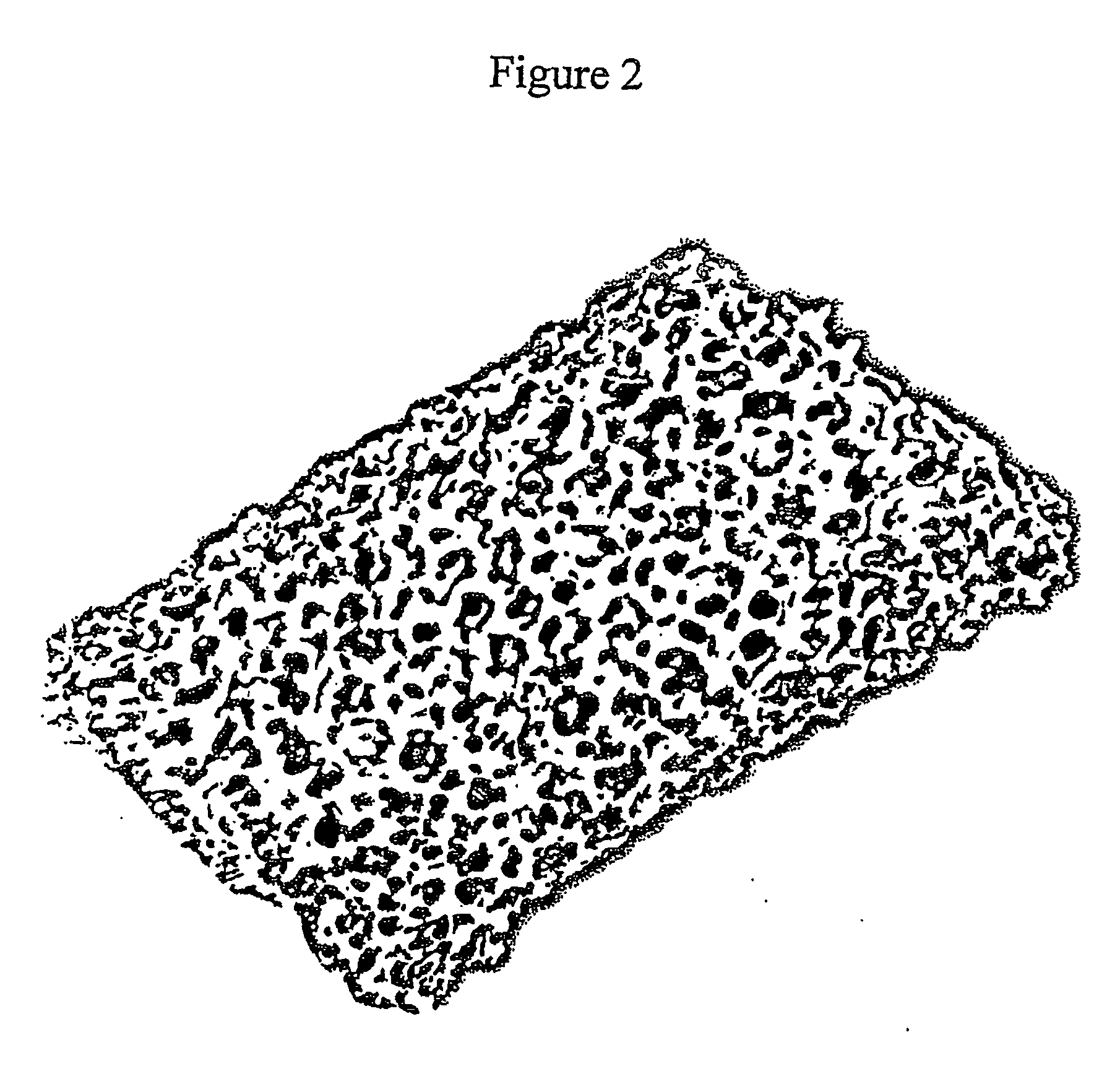
[0068]FIGS. 1 and 2 illustrate two separate embodiments of the element. The sponge-like element is made from polyurethane that is porous, low density, non-degradable, absorptive and resistant to wear and tear by the constant beating of the heart. The sponge-like element has a low inflammatory potential and supports seeding or impregnation with cellular phenotypes. The compliance of the sponge-like element matches the mechanical properties of the myocardium. Compliance matching of the sponge-like element with myocardium tissue would reduce or prevent chronic inflammation in the myocardial tissue surrounding the implant. The pores 2 of the sponge-like element are between 50 and 200 microns in diameter, and are interconnected throughout the element. Recess 3 (in FIG. 1) extends along a substantial portion of the length of the element. FIG. 2 illustrates a similar sponge-like element but without the recessed portion.

[0069] In one embodiment, the recess of the element illustrated in FIG...


PUM


Abstract

A method for treating ischaemic tissue comprising cutting the tissue to form a wound, and locating a sponge-like element (1) structured to receive blood and to comply with the movement of the tissue, in contact with a source of blood whereby the element (1) receives blood from the source of blood to thereby promote tissue growth and angiogenesis throughout and beyond the element (1).

Description

FIELD OF THE INVENTION [0001] The invention relates to the use of a sponge-like element to promote tissue growth and angiogenesis for treatment of ischaemic tissue, particularly, ischaemic cardiac tissue. BACKGROUND OF THE INVENTION [0002] The growth and maintenance of healthy tissue is dependent on vascularisation within the tissue to provide the necessary requirements for constituent cell growth and maintenance of the tissue. Consequently, circumstances which lead to depletion or loss of vascularisation may lead to reduction in blood flow to the tissue and reduced tissue function. [0003] Diseases that result from a reduction of blood flow and as a result, reduced tissue function, constitute a significant health problem in industrialised countries. For example, ischaemic heart disease results from depleted blood flow in the heart muscle. The loss of blood flow to regions of the heart muscle may result in reduction of heart muscle function, or damage to the heart muscle as is the ca...

Claims


Application Information

Patent Timeline
Patent Type & Authority Applications(United States)
IPC IPC(8): A61B19/00A61B17/00A61B17/34A61F2/00
CPCA61B17/34A61B17/3468A61B2017/00243A61B2017/00247A61B2018/00392A61F2/0077
Inventor MCLACHLAN, CRAIG
Owner MCLACHLAN CRAIG
Learn More