Mechanical clamping jaw applied to bearing ring

A technology of mechanical grippers and bearing rings, which is applied in the field of mechanical grippers, can solve the problems of affecting the quality of bearing rings, insufficient lifting of bearing rings, and inconvenient clamping of circular inner rings or outer rings, etc., to achieve Small effect on surface quality, easy to clamp

Inactive Publication Date: 2017-06-13
KUNSHAN YYB AUTOMATION EQUIP
View PDF6 Cites 8 Cited by
  • Summary
  • Abstract
  • Description
  • Claims
  • Application Information

AI Technical Summary

Problems solved by technology

The existing bearing manufacturing production is gradually changing from manual to fully automated. Robots and manipulators play a vital role in the fully automated production of bearings. Gripper, although its mechanical jaw has good versatility, it is inconvenient to clamp the inner or outer

Method used


Image

  • Mechanical clamping jaw applied to bearing ring
  • Mechanical clamping jaw applied to bearing ring
  • Mechanical clamping jaw applied to bearing ring

Examples


Embodiment Construction

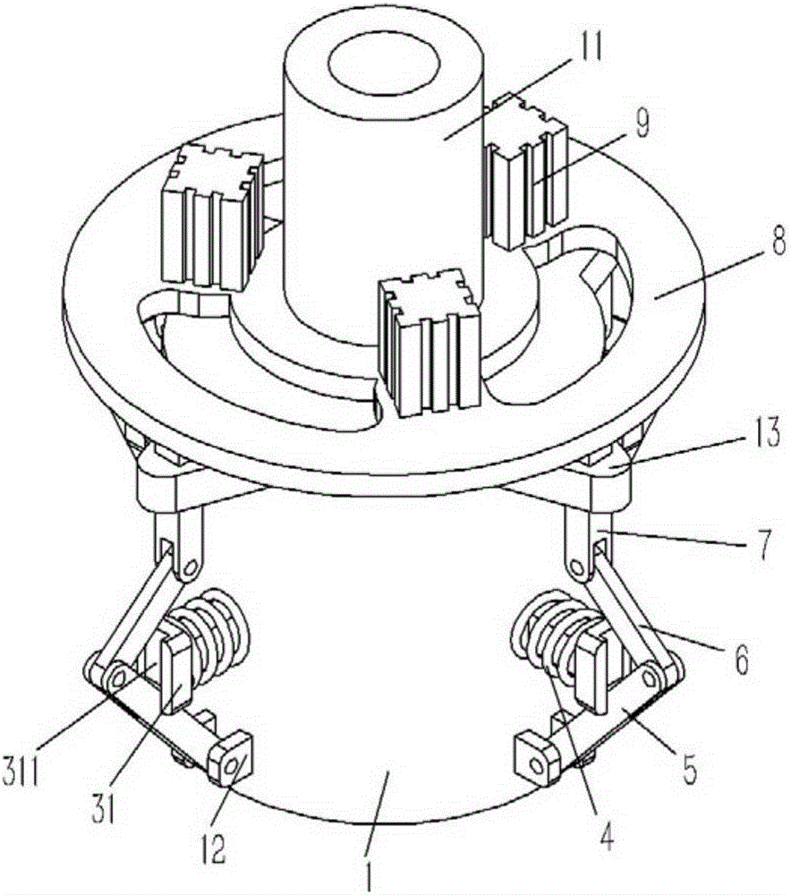
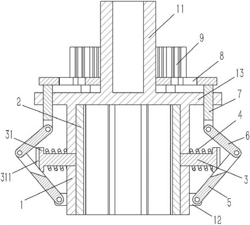
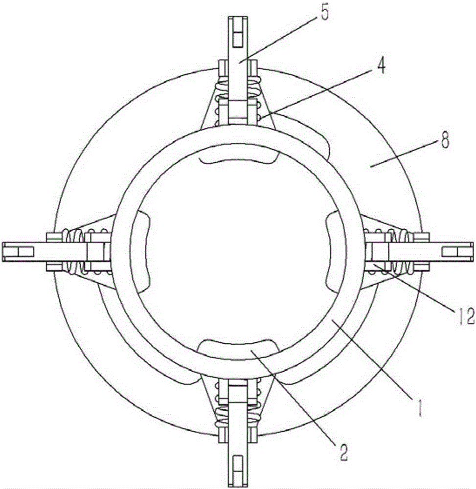
[0022] Example: see Figures 1 to 4 As shown, a mechanical gripper applied to a bearing ring includes a sleeve 1, a circular mounting column 11 is formed in the center of the upper end surface of the sleeve 1, and a plurality of hinge seats 12 are formed on the outer wall of the lower end of the sleeve 1. A plurality of lugs 13 are formed on the outer wall of the upper end of the sleeve 1, and a plurality of arc-shaped clips 2 abut against the inner wall of the sleeve 1. The clips 2 are evenly distributed in a ring around the central axis of the sleeve 1, and the clips A horizontal prism 3 is fixed on the outer wall of 2, and the outer end of the prism 3 passes through the sleeve 1 to form a stopper 31. The prism 3 is inserted with a compression spring 4, and the two ends of the compression spring 4 are respectively pressed against On the outer wall of the sleeve 1 and the stopper 31, a vertical slot 311 is formed on the stopper 31, and an inclined pressing rod 5 is inserted i...


PUM


Abstract

The invention discloses a mechanical clamping jaw applied to a bearing ring. A plurality of circular-arc-shaped clamping pieces abut against the inner wall of a sleeve of the clamping jaw and are annularly and uniformly distributed around the central axis of the sleeve, a horizontal prism is fixed to the outer wall of each clamping piece, the outer end of the prism penetrates through the sleeve to form a stop block, the prism is sleeved with a compression spring in an inserted mode, two ends of the compression spring abut against the outer wall of the sleeve and the stop block respectively in a pressing mode, a vertical inserting groove is formed in the stop block, an obliquely arranged compression rod is inserted in the inserting groove in a connected mode, the lower end of the compression rod is hinged to a hinge seat, the upper end of the compression rod is hinged to one end of a connecting rod, the other end of the connecting rod is hinged to a vertical pull rod, the upper end of the pull rod penetrates through a supporting lug to be fixed to a lifting plate, a plurality of lifting air cylinders are fixed to the lifting plate, and piston rods of the lifting air cylinders penetrate through the lifting plate to be fixed to the upper end face of the sleeve. The mechanical clamping jaw with the new structure is provided for a robot for bearing production, facilitates bearing ring clamping and has small surface quality influence on the bearing ring during clamping.

Description

[0001] Technical field: [0002] The invention relates to the technical field of robots for bearing production, and more specifically relates to a mechanical gripper applied to bearing rings. [0003] Background technique: [0004] Bearings are components that fix and reduce the friction coefficient of loads in the process of mechanical transmission, and are an important part of contemporary mechanical equipment. The existing bearing manufacturing production is gradually changing from manual to fully automated. Robots and manipulators play a vital role in the fully automated production of bearings. Gripper, although its mechanical jaw has good versatility, it is inconvenient to clamp the inner or outer ring of the ring. There are only two points of contact between the jaw and the inner or outer ring. The clamping force is small and the friction It is not enough to lift the bearing ring, and when the clamping force is large, it is easy to affect the quality of the inner or oute...

Claims


Application Information

Patent Timeline
IPC IPC(8): B25J15/00
CPCB25J15/00
Inventor 李胜利
Owner KUNSHAN YYB AUTOMATION EQUIP
Why Eureka
Try Eureka