Medical image film storage device

A medical imaging and storage device technology, applied in the direction of internal accessories, etc., can solve the problems of inconvenient access, easy bending and deformation, and inconvenient portability, etc., to achieve easy insertion and access, not easy to bend and deform, Portable and portable effect

Inactive Publication Date: 2017-06-13
THE FIRST PEOPLES HOSPITAL OF CHANGZHOU
16 Cites 2 Cited by

AI-Extracted Technical Summary

Problems solved by technology

[0007] Although this type of medical imaging film portable box solves the problem of being convenient to separate and place the medical imaging film so as to avoid the problem of sticking and the messy placement of the medical imaging film, it still has certain defects and deficiencies.
[0008] Specifically, on the one hand, the size of medical imaging film is generally about 8 inches * 10 inches, and its length and width are relatively large, so that the height of the corresponding box generally needs to be increased to more than 8 inches. In this way, then It is inconvenient to...

Method used

Furthermore, in this technical solution, on the one hand, the power switch key 1004 is accommodated in the button hole 10011, so that the hiding effect is good, so that the upper cover plate 10 does not need to be taken when covering it Or when inserting the medical imaging film, the power switch key 1004 is unlikely to be touched and light up the white LED panel light 90 unintentionally. On the other hand, when using the present invention, the upper cover plate 10 to a certain angle, so that the inner end face of the upper cover plate 10 is facing the doctor, and then the medical image film is pasted on the outer end face of the transparent glass protective screen 110, so that its side is clamped on the strip magnetic Between the suction block 120 and the bar-shaped iron block 130 , the medical image film to be viewed is bonded and fixed, so that it is more difficult to slip off, and furthermore, the use effect of the present invention can reach the best.
[0071] In view of this, on the one hand, the arc-shaped groove 4021 provided in the middle of the right side of the bag surface 402 facilitates the insertion and removal of the medical imaging film and facilitates the operation.
[0072] On the other hand, because the upper end surface of the bag bottom 401 is not covered by the bag surface 402, there is an indicator label 4011 for marking the information of the medical imaging film stored in the corresponding film storage bag 40, By referring to the corresponding indication label 4011, the medical image film to be retrieved can be quickly found, which saves time and effort.
[0081] Moreover, the power switch key 1004 is accommodated in the button hole 10011, so that the hiding effect is good, so that when the cover plate 10 is closed without taking or inserting the medical imaging film, the The power switch key 1004 will not be touched to light up the white LED panel lamp 90 unintentionally.
[0096] In addition, in this technical solution, on the one hand, an arc-shaped groove 4021 is provided in the middle part of the right side of the bag surface 402, which facilitates the insertion and rem...

Abstract

The invention discloses a medical image film storage device. The medical image film storage device comprises an upper cover plate, a lower cover plate, a vertical connecting plate and a plurality of film storage bags, wherein the upper edge of the vertical connecting plate is rotationally connected with the left side of the upper cover plate, and the lower edge is fixedly connected with the left side of the lower cover plate; the film storage bags are stacked on the lower cover plate from top to bottom; the left sides of the film storage bags are all fixedly connected with the right side wall of the vertical connecting plate; inserting openings for inserting medical image films are formed in the right sides of the film storage bags. The medical image film storage device disclosed by the invention has the effects that one medical image film is stored in one film storage bag, so that separate placement of multiple medical image films is realized, and adhesion is avoided; the film storage bags are fixed through a stacking way, so that the problem of disorder storage does not exist; the medical image films are horizontally stored, so that bending deformation is not easy to cause; the medical image film storage device is not provided with a separating plate, so that the whole weight is greatly reduced, and the using effect is good.

Application Domain

Technology Topic

Image

  • Medical image film storage device
  • Medical image film storage device
  • Medical image film storage device

Examples

  • Experimental program(1)

Example Embodiment

[0059] The technical solutions of the present invention will be described in detail below with reference to the drawings and specific embodiments, so as to understand the essence of the present invention more clearly and intuitively.
[0060] Combine figure 1 , figure 2 , image 3 , Figure 4 , Figure 5 and Image 6 Shown
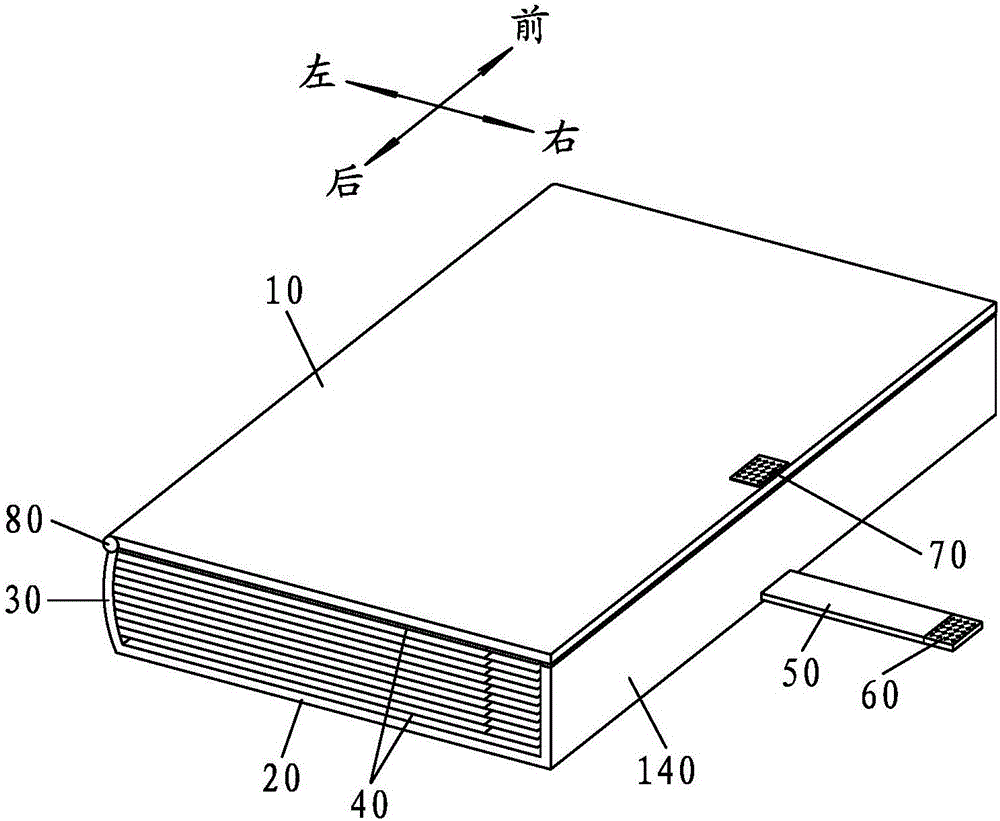
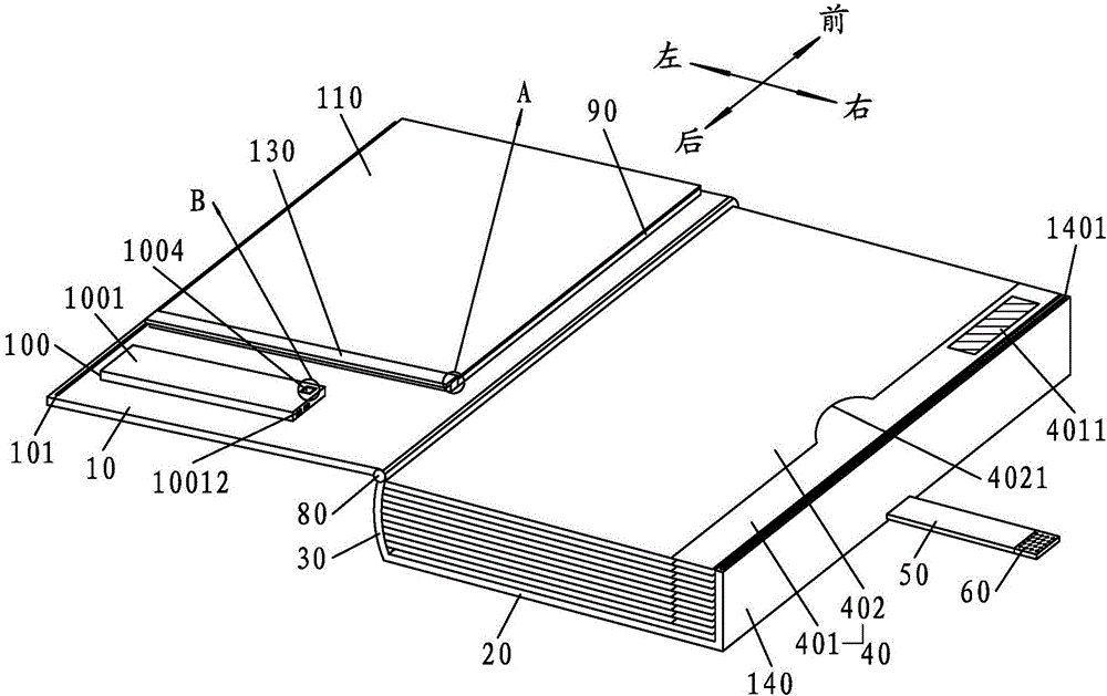
[0061] A medical imaging film storage device provided by the present invention includes an upper cover plate 10, a lower cover plate 20, a vertical connecting plate 30, and a plurality of film storage bags 40;
[0062] Wherein, the upper edge of the vertical connecting plate 30 is rotatably connected to the left side of the upper cover plate 10, and the lower edge is fixedly connected to the left side of the lower cover plate 20; the plurality of film storage bags 40 are connected from the top Stacked on the lower cover plate 20 in turn from the bottom, and the left side of the plurality of film storage bags 40 are fixedly connected with the right side wall of the vertical connecting plate 30, and the plurality of film storage bags 40 On the right side, there are openings for inserting medical imaging film.
[0063] Based on the foregoing, it can be understood that the medical imaging film storage device provided by the present invention, in specific implementation, on the one hand, is provided with a plurality of film storage bags 40, and each film storage bag 40 stores one film. Medical imaging film, that is, to realize the separation and placement of multiple medical imaging films, so as to avoid sticking, resulting in blurring, and a plurality of film storage bags 40 are fixed in a stacked manner, so that multiple medical imaging films are not stored Messy question.
[0064] On the other hand, when the medical imaging film does not need to be taken, the upper cover plate 10 and the lower cover plate 20 pack a plurality of laminated film storage bags 40 containing medical imaging films, so that the protection effect is good , So as to prevent the stored medical imaging film from being scratched by the touch of foreign objects.
[0065] In addition, the corresponding medical imaging film is stored horizontally, which makes it difficult to bend and deform. However, the present invention is not provided with partitions, which greatly reduces the overall weight and makes it easy to carry and carry.
[0066] Furthermore, the present invention has strong practicability and good use effect.
[0067] It should be emphasized that, in this technical solution, each of the film storage bags 40 includes a bottom 401 located in the lower layer and a bag surface 402 located in the upper layer;
[0068] Wherein, the width from the left side to the right side of the bag bottom 401 is greater than the width from the left side to the right side of the bag surface 402; the left side of the bag surface 402 and the bag bottom 401 The left side of the bag surface is flush with each other, and they are all fixedly connected to the right side wall of the vertical connecting plate 30; the middle of the right side of the bag surface 402 is provided with an arc-shaped groove 4021.
[0069] In addition, the area on the upper end surface of the bag bottom 401 that is not covered by the bag surface 402 is attached with an indicator label 4011 for indicating the information of the medical imaging film stored in the corresponding film storage bag 40; on the indicator label 4011 The marked information includes the name of the filmmaker of the medical imaging film stored in the corresponding film storage bag 40, the gender of the filmmaker, the photo of the filmmaker, the age of the filmmaker, the filming time, and the filming location of the filmmaker.
[0070] And the middle of the right side of the lower cover plate 20 is provided with a flat fixing belt 50 extending outwards, the end of the flat fixing belt 50 is connected with a male velcro 60; the outer end surface of the upper cover plate 10 A female Velcro 70 for bonding the male Velcro 60 is fixedly arranged in the middle part near the right side thereof.
[0071] In view of this, on the one hand, the arc-shaped groove 4021 is provided in the middle of the right side of the bag surface 402, which facilitates the insertion and retrieval of medical imaging films, and facilitates the operation.
[0072] On the other hand, because the upper end surface of the bag bottom 401 is not covered by the bag surface 402, an indication label 4011 is attached to indicate the information of the medical imaging film stored in the corresponding film storage bag 40. Tag 4011 can quickly find out the medical imaging film that needs to be taken, saving time and effort.
[0073] In addition, when the male Velcro 60 and the female Velcro 70 are bonded, the right side of the upper cover plate 10 and the right side of the lower cover plate 20 are fixed, so that the film storage bag 40 The medical imaging film stored inside will not slip out and fall.
[0074] Furthermore, the use effect of the present invention can be greatly improved.
[0075] It should be noted that in this embodiment, the upper edge of the vertical connecting plate 30 and the left side of the upper cover plate 10 are rotatably connected by a damping rotating shaft 80. That is, the damping rotation shaft 80 has a certain damping effect, so that after the upper cover plate 10 is rotated to a certain angle, it can be opened and fixed at a certain angle. The corresponding damping rotation shaft 80 is in the prior art. Give details.
[0076] Moreover, in this embodiment, the inner end surface of the upper cover plate 10 is fixedly provided with a white LED flat light 90 from its front end to the middle, and the rear portion of the inner end surface of the upper cover plate 10 is fixedly provided with a control The main control device 100 of the white LED flat light 90;
[0077] Wherein, the main control device 100 includes a flat housing 1001, a main controller 1002 arranged inside the flat housing 1001, a power supply module 1003, and a power switch 1004 arranged outside the flat housing 1001 The white LED panel light 90, the power module 1003 and the power switch 1004 are respectively connected to the main controller 1002.
[0078] And in specific implementation, the outer end surface of the flat housing 1001 is provided with a button hole 10011, the power switch key 1004 is received in the button hole 10011; the outer end surface of the white LED flat light 90 is provided with a transparent The glass protective screen 110, the outer end surface of the flat housing 1001 is flush with the outer end surface of the transparent glass protective screen 110.
[0079] In view of the above, it is clear that, on the one hand, when the upper cover plate 10 is axially rotated around the damping rotation shaft 80 at a certain angle, the upper cover plate 10 will be opened and fixed at a certain angle, so that The medical imaging film can be taken from the corresponding film storage bag 40 or inserted into the corresponding film storage bag 40 without fully opening one hundred and eighty degrees, which makes the operation convenient.
[0080] On the other hand, after controlling the upper cover plate 10 to open and fix it at a certain angle, press the power switch 1004 to light up the corresponding white light LED flat light 90, and the doctor can attach the medical imaging film to the corresponding white light LED The outer end surface of the transparent glass protection screen 110 outside the flat lamp 90 is used to view the medical imaging film, which facilitates the diagnosis of the doctor, and also prevents the doctor from holding the medical imaging film for a long time in both hands for viewing and reading and causing soreness.
[0081] In addition, the power switch 1004 is housed in the button hole 10011, so that the hiding effect is good, so that when the upper cover plate 10 is closed without taking or inserting the medical imaging film, the power switch 1004 will not be touched and inadvertently light up the white LED flat light 90.
[0082] Therefore, the use effect of the present invention can be further improved.
[0083] It needs to be supplemented that in this technical solution, the white LED flat light 90 is preferably a square structure, and the width from the front side to the rear side of the white LED flat light 90 is equal to or greater than the bag surface 402 The width from the left to the right;
[0084] The inner end surface of the upper cover plate 10 is fixedly provided with a strip-shaped magnetic block 120 on the rear side of the white light LED flat light 90, and the strip-shaped magnetic block 120 and the rear side of the white light LED flat light 90 The outer end surface of the strip-shaped magnetic block 120 is flush with the outer end surface of the transparent glass protective screen 110, and the outer end surface of the strip-shaped magnetic block 120 is attracted by a strip-shaped iron block 130.
[0085] In this way, when using the present invention, the upper cover plate 10 is opened to a certain angle so that the inner end of the upper cover plate 10 faces the doctor, and then the medical imaging film is attached to the outside of the transparent glass protective screen 110 The end face is so that the front is facing the eyes of the doctor, and then the strip-shaped iron block 130 is taken, so that the side edge of the corresponding medical imaging film is pressed against the upper end surface of the strip-shaped magnetic block 120, and then the strip shape is restored The iron block 130 is attracted to the strip-shaped magnetic block 120, so that the side of the corresponding medical imaging film is clamped between the strip-shaped magnetic block 120 and the strip-shaped iron block 130, even if The medical imaging film that needs to be viewed is laminated and fixed, making it more difficult to slip off, so that it is better to save the pinch and fix with both hands.
[0086] Furthermore, the use effect of the present invention can reach the best.
[0087] It should be further supplemented that, in the specific implementation, the longitudinal section of the strip-shaped iron block 130 is formed into an inverted L-shaped structure, including a horizontal first suction part 1301 and a vertical second suction part 1302, so The lower bottom surface of the first attraction portion 1301 is attracted to the upper end surface of the strip-shaped magnetic attraction block 120, and the front side surface of the second attraction portion 1302 is attracted to the rear side surface of the strip-shaped magnetic attraction block 120 Closely, the second suction part 1302 can serve as a suction limit and can be used as a handle.
[0088] Moreover, in this embodiment, the right side of the lower cover plate 20 is vertically fixed with a partition 140 integrally formed with the same height as the vertical connecting plate 30, and the upper part of the partition 140 A magnetic stripe A1401 is fixedly arranged on the end surface, and a magnetic stripe B101 with opposite polarity to the magnetic stripe A1401 for attracting the magnetic stripe A1401 is fixedly arranged on the right side of the inner end surface of the upper cover plate 10 in the front-to-back direction;
[0089] When the upper cover plate 10 is rotated to close the film storage bag 40 on the uppermost layer, the magnetic stripe A1401 and the magnetic stripe B101 attract each other, and the upper cover plate 10 and the partition 140 Suck and fix.
[0090] The corresponding partition 140 can cover the right side of the plurality of film storage bags 40, so that the medical imaging films stored in the plurality of film storage bags 40 will not slip off.
[0091] At the same time, in specific implementation, the power supply module 1003 is a rechargeable power supply, and the side of the flat housing 1001 is provided with a USB charging interface 11012 for charging the rechargeable power supply. The USB charging interface 11012 is connected to the The power supply module 1003 is connected.
[0092] In this way, the rechargeable power source is charged intermittently through the USB charging interface 11012, which makes the present invention work uninterrupted.
[0093] In addition, the present invention can also be used as a flat-panel lamp to provide lighting at night, so that it can be integrated and multi-purpose and has more comprehensive functions. The overall structure of the present invention is similar to the traditional photo album structure. It also makes the whole compact and easy to carry. The present invention can be taken home to view the medical imaging film, making it convenient for doctors to work.
[0094] Other embodiments, etc., are not illustrated here.
[0095] In summary, the medical imaging film storage device provided by the present invention, in specific implementation, on the one hand, is provided with a plurality of film storage bags 40, and each film storage bag 40 stores one medical imaging film, namely The separated placement of multiple medical imaging films is realized so as to avoid sticking and blurring. The plurality of film storage bags 40 are fixed in a stacked manner, so that there is no problem of messy storage of multiple medical imaging films. On the one hand, when the medical imaging film does not need to be taken, the upper cover plate 10 and the lower cover plate 20 wrap a plurality of laminated film storage bags 40 containing medical imaging films, so that the protection effect is good. This prevents the stored medical imaging film from being scratched by the touch of foreign objects, and the corresponding medical imaging film is stored horizontally, so that it is not easy to bend and deform. However, the present invention does not provide the partition 140, which makes the overall weight large. The lightening makes it convenient to carry and carry. Furthermore, the present invention has strong practicability and good use effect.
[0096] In addition, in the present technical solution, on the one hand, an arc-shaped groove 4021 is provided in the middle of the right side of the bag surface 402, which facilitates the insertion and retrieval of medical imaging films, and makes the operation convenient. On the other hand, the The area on the upper end surface of the bag bottom 401 not covered by the bag surface 402 is glued with an indicator label 4011 for indicating the information of the medical imaging film stored in the corresponding film storage bag 40. Compare with the corresponding indicator label 4011, you can quickly Find out the medical imaging film that needs to be taken, which saves time and effort. Moreover, when the male velcro 60 and the female velcro 70 are bonded, the right side of the upper cover plate 10 and the lower The right side of the cover plate 20 is fixed so that the medical imaging film stored in the film storage bag 40 will not slip out and fall, and further, the use effect of the present invention can be greatly improved.
[0097] Again, in this embodiment, on the one hand, the upper edge of the vertical connecting plate 30 and the left side of the upper cover plate 10 are rotatably connected by a damping rotation shaft 80, which is rotatably connected around the damping rotation shaft 80. When the upper cover plate 10 is rotated to a certain angle, the upper cover plate 10 will be opened and fixed at a certain angle, so that the medical image can be taken from the corresponding film storage bag 40 without fully opening one hundred and eighty degrees. The film or the medical imaging film is inserted into the corresponding film storage bag 40, which makes the operation convenient. On the other hand, the inner end surface of the upper cover plate 10 is fixedly provided with a white LED flat light 90 from the front end to the middle part thereof to control the After the upper cover plate 10 is opened and fixed to a certain angle, the doctor can attach the medical imaging film to the outer end surface of the transparent glass protective screen 110 outside the corresponding white LED flat light 90 to view the medical imaging film, which facilitates the doctor’s diagnosis It also enables the doctor to avoid soreness caused by holding the medical image film in both hands for a long time for viewing, so that the use effect of the present invention can be further improved.
[0098] Furthermore, in the present technical solution, on the one hand, the power switch key 1004 is housed in the key hole 10011, so that the hiding effect is good, so that the upper cover plate 10 does not need to be taken, taken, or inserted when the cover plate 10 is covered. In the case of medical imaging film, the power switch key 1004 will not be touched and the white LED panel lamp 90 will be lighted unintentionally. On the other hand, when the present invention is used, the upper cover plate 10 is opened to a certain extent Angle so that the inner end face of the upper cover plate 10 faces the doctor, and then the medical imaging film is attached to the outer end face of the transparent glass protective screen 110, so that its side is clamped on the strip-shaped magnetic block 120 Between the strip-shaped iron block 130, even the medical imaging film that needs to be viewed is bonded and fixed, making it more difficult to slip off, and further, the use effect of the present invention can reach the best.
[0099] Correspondingly, the overall structure of the present invention is simple, easy to implement, easy to operate, strong in practicability, and strong in specificity. In the improvement of the structure and the improvement of technology, there is no need to increase too much cost, so that the present invention is bound to be very good. The market value of this invention will be very popular and can be effectively popularized.
[0100] The above descriptions are only the preferred embodiments of the present invention, and do not limit the scope of patent protection of the present invention. Any transformation of the equivalent structure or equivalent process made by the content of the description and drawings of the present invention, or directly or indirectly applied to other Related technical fields are included in the scope of patent protection of the present invention in the same way.

PUM

no PUM

Description & Claims & Application Information

We can also present the details of the Description, Claims and Application information to help users get a comprehensive understanding of the technical details of the patent, such as background art, summary of invention, brief description of drawings, description of embodiments, and other original content. On the other hand, users can also determine the specific scope of protection of the technology through the list of claims; as well as understand the changes in the life cycle of the technology with the presentation of the patent timeline. Login to view more.

Similar technology patents

Air bag restraint device with a plurality of inflating matters

InactiveCN102371962AGood protectionEliminate the possibility of burstingPedestrian/occupant safety arrangementGas generatorExternal pressure
Owner:YANFENG KEY SHANGHAI AUTOMOTIVE SAFETY SYST

Classification and recommendation of technical efficacy words

  • Good protection
  • Not easy to bend and deform

Forming of error correction data

ActiveUS20060075321A1Good protectionLow complexityError preventionCode conversionEqual sizeData reconstruction
Owner:INTELLECTUAL VENTURES I LLC

Ballistic shield composites with enhanced fragment resistance

ActiveUS8080486B1Good protectionHigh mobility/maneuverabilityArmourProtective equipmentFibrous layerWoven fabric
Owner:HONEYWELL INT INC

Novel distribution box

Owner:天津津通华电气设备有限公司

Coiling shaft, end cover, safety belt coiling device and safety belt assembly

InactiveCN102837665ANot easy to bend and deformThe overall stress situation is simplifiedBelt retractorsEngineeringMechanical engineering
Owner:和励科技有限公司

Wind power blade with specially-made blade tip plate

Owner:重庆交通大学绿色航空技术研究院

Shopping basket

ActiveCN101913453AGood stabilityNot easy to bend and deformContainer handlesExternal fittingsShopping basketEngineering
Owner:SHANGHAI HONGYAN RETURNABLE TRANSIT PACKAGINGS CO LTD
Why Eureka
Try Eureka