Spinning machine and false twist unit

A textile machine and false twisting technology, applied in the direction of textiles and papermaking, to achieve the effect of reducing tension difference and reducing tension difference

Inactive Publication Date: 2017-06-13
MASCHINENFABRIK RIETER AG
View PDF1 Cites 4 Cited by
  • Summary
  • Abstract
  • Description
  • Claims
  • Application Information

AI Technical Summary

Problems solved by technology

This also increases the number of strand breaks at start-up, which is unacceptable

Method used


Image

  • Spinning machine and false twist unit
  • Spinning machine and false twist unit
  • Spinning machine and false twist unit

Examples


Embodiment Construction

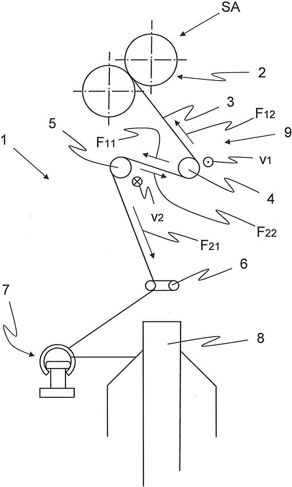
[0080] exist figure 1 The weaving unit 1 of the weaving machine 10 is schematically and partially shown in FIG. The delivery roll pair 2 of the drafting unit, not shown, supplies the ply strand 3 and forms the drafting unit output SA. The strand 3 turns around a first plastic belt 4 and then around a second plastic belt 5 . Subsequently, the ply thread 3 passes through the twist stopper 6 and the traveler 7, and is wound on the bobbin 8 at last. The first plastic belt 4 and the second plastic belt 5 form a false twist device 9 . The two plastic belts 4 and 5 can refer to two separate belts 4 and 5 or to stretching and pushing return sections of a single belt.

[0081] The first plastic belt 4 and the second plastic belt 5 or both runs have opposite directions of movement. Since the ply thread 3 lies on two belts 4 and 5 moving in opposite directions, the yarn is stretched in one direction by one return and in the other direction by the other return. The ply wire 3 is def...


PUM


Abstract

A spinning machine, in particular a ring-spindle spinning machine is provided with a plurality of units (1) arranged side by side. Each unit (1) is provided with a traction mechanism moving a fiber belt, a spinning device twisting the moving fiber belts into a twine (3), and a false twist unit (9) arranged between the traction mechanism and the spinning device; the false twisting device (9) is provided with at least one belt (11) driven by a driving device; the belt basically extends along the twine (3) in a transverse direction; the twine (3) particularly winds two return sections (4,5) opposite to each other of the belt (11) in a Z shape or an S shape; and the at least one belt (11) extends between the at least one driving device and the steering device along a plurality of units (1) of a spinning machine (10). According to the invention, at least one assisting device (30) is arranged between the at least one driving device and the steering device to cooperatively guide and / or drive the at least one belt (11).

Description

technical field [0001] The invention relates to a textile machine, in particular a ring spinning machine, having a plurality of units arranged side by side, wherein each unit has a drafting mechanism for transporting a fiber strip; Spinning device; False twisting device arranged between the drafting device and the spinning device, which has at least one belt driven by means of a drive, which belt extends transversely to the plying thread, and the plying thread is wound around this or in particular in a Z-shape Two opposite return sections of these belts, and said at least one belt extends along multiple units of the textile machine between the drive device and the steering device; and the corresponding false twist device, which can be installed in the textile On the machine, so that obtain by the textile machine of the present invention. Background technique [0002] A textile machine is known from WO 2010 / 015185 A1, in which a false twist device is arranged between a draft...

Claims


Application Information

Patent Timeline
IPC IPC(8): D02G1/08
CPCD02G1/085D01H7/926D02G1/04D02G1/0213
Inventor G·斯塔莱克
Owner MASCHINENFABRIK RIETER AG
Why Eureka
Try Eureka