Height adjustable sewing machine rack with extension plate
An adjustable sewing machine technology, which is applied to sewing machine components, sewing equipment, textiles and papermaking, etc., can solve the problems of low efficiency, inability to adjust the height, and inability to meet the needs of users with different heights, so as to facilitate the placement of fabrics and increase area effect
- Summary
- Abstract
- Description
- Claims
- Application Information
AI Technical Summary
Problems solved by technology
Method used
Image

Examples
Embodiment Construction
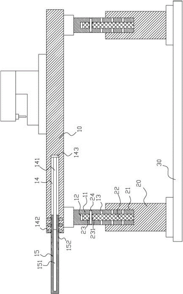
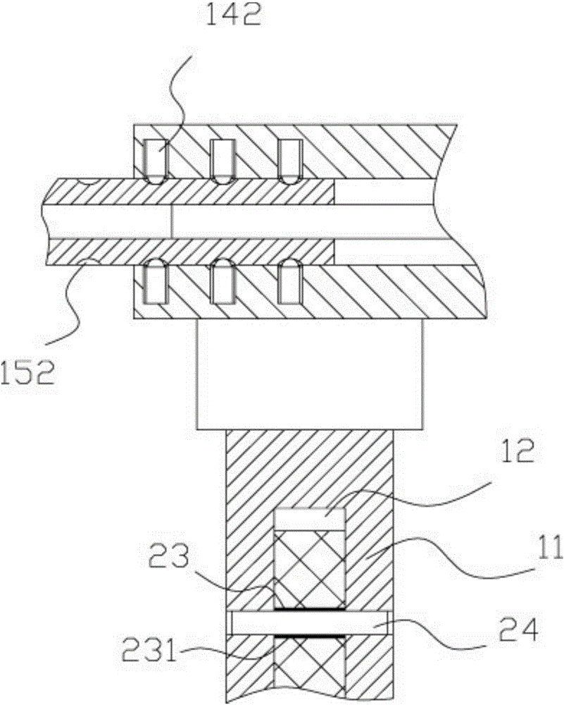
[0022] Examples, see e.g. Figure 1 to Figure 2 As shown, a height-adjustable sewing machine stand with an extension plate includes an upper platform 10, and vertical adjustment columns 11 are fixed on both sides of the bottom surface of the upper platform 10, and the middle part of the bottom surface of the vertical adjustment column 11 has a central through hole 12. The vertical adjustment column 11 is formed with a plurality of vertically arranged horizontal limiting through holes 13, and the middle part of the horizontal limiting through holes 13 passes through the central through hole 12;
[0023] The vertical adjustment column 11 is inserted into the socket 21 provided in the middle of the top surface of the lower support column 20, and the middle of the top surface of the socket 21 is fixed with an extension insertion rod 22, and the extension insertion rod 22 is inserted and sleeved in the central through hole 12. , the upper part of the extended insertion rod 22 has a...
PUM
 Abstract
Description
Claims
Application Information
PatSnap Eureka turns technology decisions into work you can execute. Powered by our Innovation Knowledge Graph, it runs expert workflows across engineering, life sciences, materials and intellectual property. Get your review-ready output in minutes.


