
Segmented hole-sweeping and retreating controlled grouting equipment for avoiding grouting walls

A retreating and controllable technology, which is applied in mining equipment, shaft equipment, shaft lining, etc., can solve the problems of affecting the grouting pressure, multiple construction procedures of the grouting wall, and easy blockage of the grouting pipe, so as to ensure the grouting Pressure, the effect of preventing the rock surface from overflowing

Active Publication Date: 2019-01-04
中铁十四局集团建筑工程有限公司
View PDF7 Cites 0 Cited by
  • Summary
  • Abstract
  • Description
  • Claims
  • Application Information

AI Technical Summary

Problems solved by technology

At present, the commonly used domestic tunnel advance curtain grouting reinforcement mostly adopts concrete grout-stop wall to stop grouting. The drilling rig makes holes many times. The material adopts cement single slurry or cement-sodium silicate double slurry. The disadvantages of this process are: The grout wall has many construction procedures, long construction period and high cost. If it is a cylindrical or spherical concrete grout stop wall, the construction will be more complicated; Unable to enter the formation, the grouting effect is difficult to guarantee; third, the ratio of double grout is not easy to control, and the grouting pipe is easy to block

Method used


Image

  • Segmented hole-sweeping and retreating controlled grouting equipment for avoiding grouting walls

Examples


Embodiment Construction

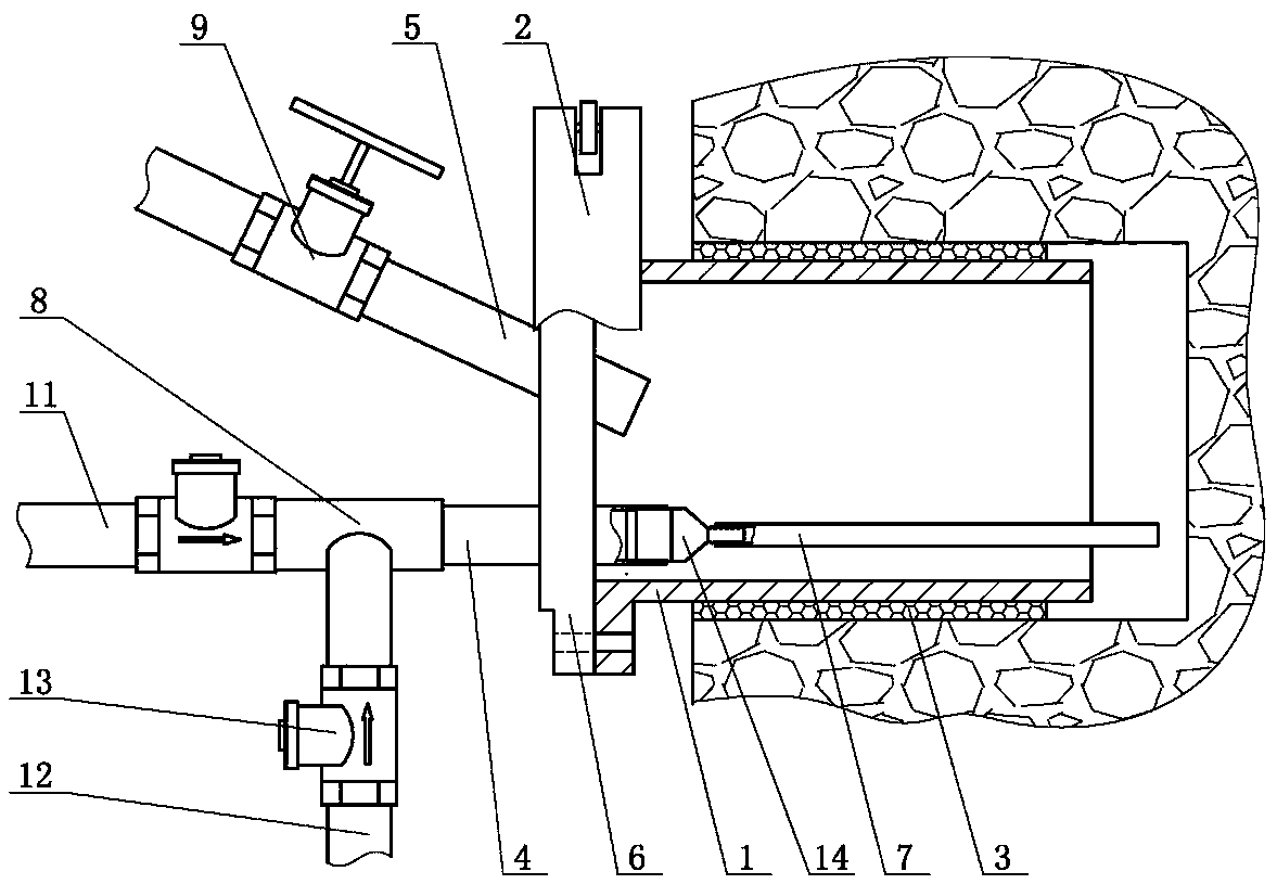
[0007] The grout-free wall segmental sweeping and retreating control grouting equipment of the present invention includes an orifice pipe 1, one end of the orifice pipe 1 is connected to a disc 6 through a quick flange joint 2, and the disc 6 is far away from the orifice pipe 1. The slurry inlet pipe 4 and the slurry outlet pipe 5 are installed on one side. The slurry inlet pipe 4 communicates with the cement slurry pipeline 11 and the control fluid pipeline 12 respectively through the slurry mixer 8. The slurry mixer 8 can adjust the mixing ratio of the cement slurry and the control fluid. A valve 9 is installed on the outlet pipe 5, the inlet pipe 4 and the outlet pipe 5 are connected to the orifice pipe 1, the orifice pipe 1 is provided with a grouting pipe 7, and one end of the grouting pipe 7 is connected to the grouting pipe 4, The length of the grouting pipe 7 is greater than the length of the orifice pipe 1 . When in use, use a drilling rig to drill a hole 2.5m-3.0m de...


PUM


Abstract

Segmented hole sweeping type retreating controllable grouting equipment free of a grout-preventing wall comprises an orifice pipe. One end of the orifice pipe is connected with a disc through a fast flange joint. A grout inlet pipe and a grout outlet pipe are arranged on the side, away from the orifice pipe, of the disc. The grout inlet pipe is connected with a cement slurry pipe and a controlling liquid pipe through a slurry mixer. The slurry mixer is capable of adjusting the mixing ratio of cement slurry to controlling liquid. A valve is installed on the grout outlet pipe. Both the grout inlet pipe and the grout outlet pipe communicate with the orifice pipe. A grout injection pipe is arranged inside the orifice pipe. One end of the grout injection pipe communicates with the grout inlet pipe. The length of the grout injection pipe is larger than the length of the orifice pipe. Both the cement slurry pipe and the controlling liquid pipe are provided with one-way valves. Since the grout-preventing wall does not need to be arranged, the problems that the existing grouting process is long in construction time and high in cost due to arrangement of the grout-preventing wall can be solved. The phenomenon that slurry overflows on the rock surface due to the development of fissures around the orifice pipe can be avoided, and grouting pressure is guaranteed.

Description

technical field [0001] The invention relates to a tunnel surrounding rock grouting construction technology, in particular to a controlled grouting equipment which prevents the grout wall from segmental sweeping and retreating. Background technique [0002] With the construction of large-scale infrastructure such as highways and railways, more and more tunnel projects are being built under complex geological conditions. When carrying out tunnel and underground engineering construction under such complex geological conditions, blasting or manual excavation will disturb the surrounding rock, change the flow state of groundwater, destroy the original mechanical state of the surrounding rock and the balance system of groundwater, and easily cause tunnel damage. Disasters such as internal collapse, mud inrush, and water gushing will cause immeasurable delays in the construction period and endanger the safety of personnel and equipment. At present, the commonly used method of stra...

Claims


Application Information

Patent Timeline
Patent Type & Authority Patents(China)
IPC IPC(8): E21D11/10
CPCE21D11/10E21D11/105
Inventor 李占先刘京增刘勇颜海建丛义营柴仁旺肖载兴韩孟杰周华阳郑彦飞陈仁强甘国军李宗田
Owner 中铁十四局集团建筑工程有限公司
Learn More