
Grouting device for high coagulation grouting material

A grouting material and grouting device technology, used in valve device, bolt installation, infrastructure engineering and other directions, can solve problems such as damage, grouting pipe diameter reduction, and difficulty in ensuring the effect, so as to reduce pressure loss and ensure injection molding. Slurry pressure to ensure the effect of transmission

Active Publication Date: 2021-06-18
QINGDAO METRO LINE 6 CO LTD +2
View PDF7 Cites 0 Cited by
  • Summary
  • Abstract
  • Description
  • Claims
  • Application Information

AI Technical Summary

Problems solved by technology

There are currently two commonly used connection methods for the joint position of segmented pipelines. One is casing connection and iron wire binding, which is difficult to guarantee the effect when the grouting pressure is high; the other is commercial joint connection, which can effectively ensure the connection effect , but the installation is time-consuming and laborious, and it is easy to cause the diameter of the grouting pipe to change and be damaged
The end of the grouting pipe is reserved at the end of the anchor cable to ensure the smooth flow of the pipeline and prevent impurities from clogging the grouting pipe when the anchor cable is installed. The pipe head is generally sealed with tape. When grouting, rely on the grouting pressure to break the tape, and it cannot be repeated. In addition, when using the grouting pipe for grouting, the grout surface is spherical, and there is a pressure loss during the flow of the grout, resulting in limited grouting effect

Method used


Image

  • Grouting device for high coagulation grouting material
  • Grouting device for high coagulation grouting material
  • Grouting device for high coagulation grouting material

Examples


Embodiment Construction

[0038] In order to make the above objects, features and advantages of the present invention more comprehensible, specific implementations of the present invention will be described in detail below in conjunction with the accompanying drawings.

[0039] In the following description, specific details are set forth in order to provide a thorough understanding of the present invention. However, the present invention can be implemented in many other ways than those described here, and those skilled in the art can make similar extensions without departing from the connotation of the present invention. Accordingly, the present invention is not limited to the specific embodiments disclosed below.

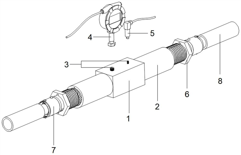
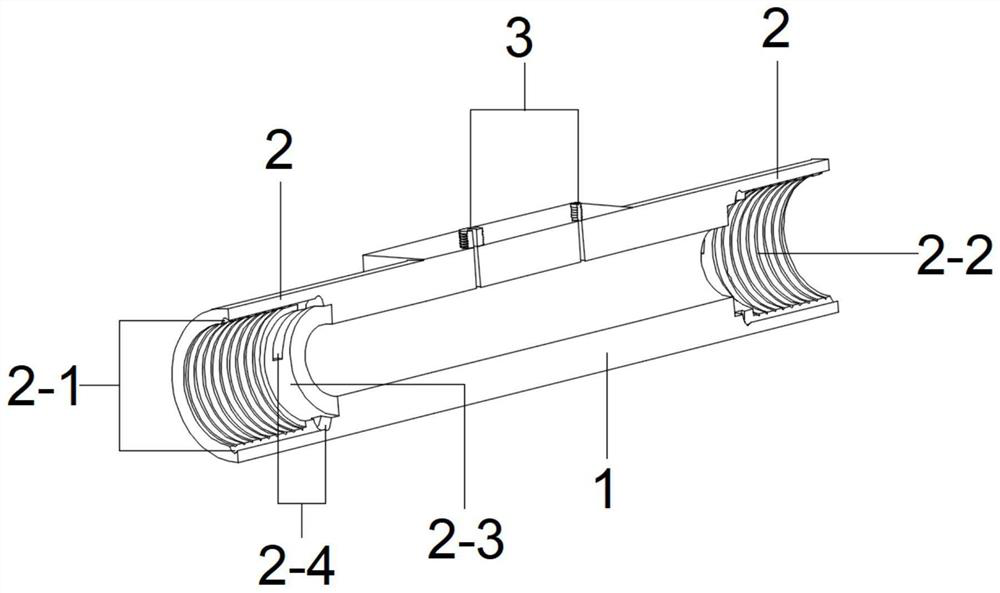
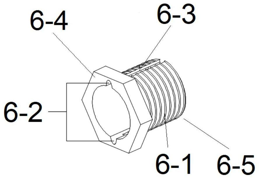
[0040] like figure 1 As shown, the grouting device for high coagulation grouting materials according to the present invention includes a grouting pipe 8, a connecting head and a self-sealing pipe head, and one end of the connecting head is connected to the grouting pump through the groutin...


PUM


Abstract

The invention relates to the field of grouting, in particular to a grouting device for highly condensable grouting materials. It includes a grouting pipe, a connecting head and a self-sealing pipe head. One end of the connecting head is connected to the grouting pump through the grouting pipe, and the other end of the connecting head is connected to the self-sealing pipe head through the grouting pipe. The grouting pipe is connected to the connecting head, The self-sealing pipe heads are all fixed and sealed connections. It is easy to install, the connection between the grouting pipe and the connector and the self-sealing pipe head is reliable, and can be reused; because the inner diameter of the connector is consistent with the inner diameter of the grouting pipe and the grout outlet on the end cap of the self-sealing pipe head is a circular grout The mouth effectively reduces the pressure loss during the grouting process, and the grouting effect is good.

Description

technical field [0001] The invention relates to the field of grouting, in particular to a grouting device for highly condensable grouting materials. Background technique [0002] With the development of grouting technology, new high coagulation grouting materials are continuously used in anchor cable construction, but the new materials have the problems of high viscosity, poor flow, and fast coagulation speed. If they are not cleaned in time after grouting, it is easy to Blocking the pipeline will affect the grouting effect. It is difficult to ensure the cleaning effect by using one-stage grouting pipeline, so it is recommended to use segmented pipeline, each section length is 4-5m. There are currently two commonly used connection methods for the joint position of segmented pipelines. One is casing connection and iron wire binding, which is difficult to guarantee the effect when the grouting pressure is high; the other is commercial joint connection, which can effectively e...

Claims


Application Information

Patent Timeline
Patent Type & Authority Patents(China)
IPC IPC(8): E21D20/02E02D5/74E02D15/02F16K15/02F16L21/08
CPCE21D20/028E02D5/74E02D15/02F16L21/08F16K15/026E02D2250/003F16L41/008F16L37/252F16L15/006
Inventor 刘泉维杨忠年李克先黄成宗超刘林胜凌贤长
Owner QINGDAO METRO LINE 6 CO LTD
Learn More