
Sleeve grouting method and grouting device thereof

A casing and wall protection casing technology, which is applied in construction, infrastructure engineering, etc., can solve the problems of low work efficiency, large gap between drill pipe and hole wall, small grouting pipe, etc., achieve convenient disassembly and use, and improve equipment utilization efficiency and ensure the effect of construction progress

Active Publication Date: 2010-06-02
SINOHYDRO BUREAU 8 CO LTD
View PDF5 Cites 0 Cited by
  • Summary
  • Abstract
  • Description
  • Claims
  • Application Information

AI Technical Summary

Problems solved by technology

Although there is no repeated phenomenon caused by hole collapse in this method, the construction process is relatively simple and the construction efficiency is high. However, due to the large gap between the drill pipe and the hole wall, the slurry is easy to emerge from the hole and cannot meet a certain pressure requirement. , the grouting quality is difficult to guarantee
The grouting device of the drill pipe grouting method is a drill pipe, which is difficult to seal and has certain restrictions on the required grouting pressure.
[0005] (3) Separate grouting pipe in the casing The grouting method refers to that after drilling to the final hole, the grouting pipe with a smaller diameter is lowered into the casing, and the gap between the casing and the grouting pipe is closed by using an orifice device. The hole can reach a certain pressure requirement, but because of the small grouting pipe in the casing, it is difficult to pour thick grout and paste grout in this process, and the grouting effect is not ideal, and this process is relatively complicated, the operation steps are cumbersome, and the work efficiency is low

Method used

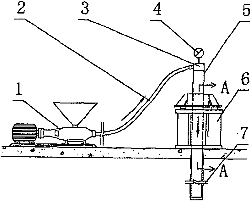
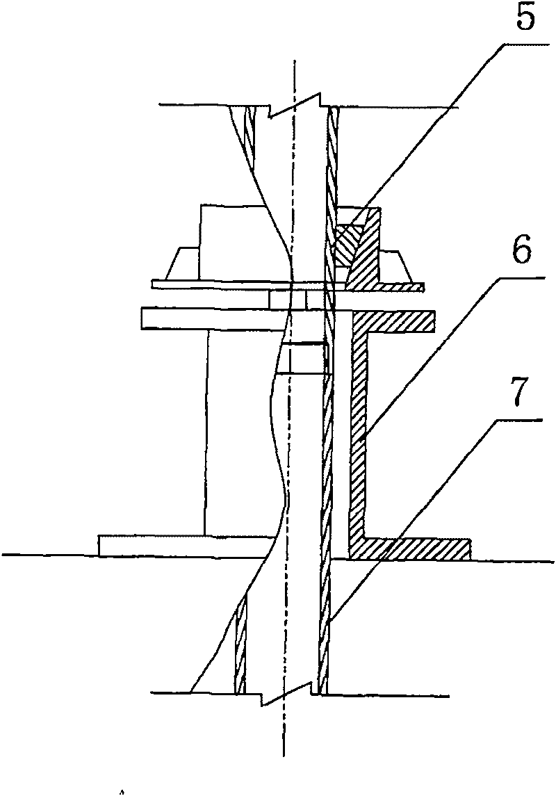

Image

  • Sleeve grouting method and grouting device thereof
  • Sleeve grouting method and grouting device thereof
  • Sleeve grouting method and grouting device thereof

Examples


Embodiment

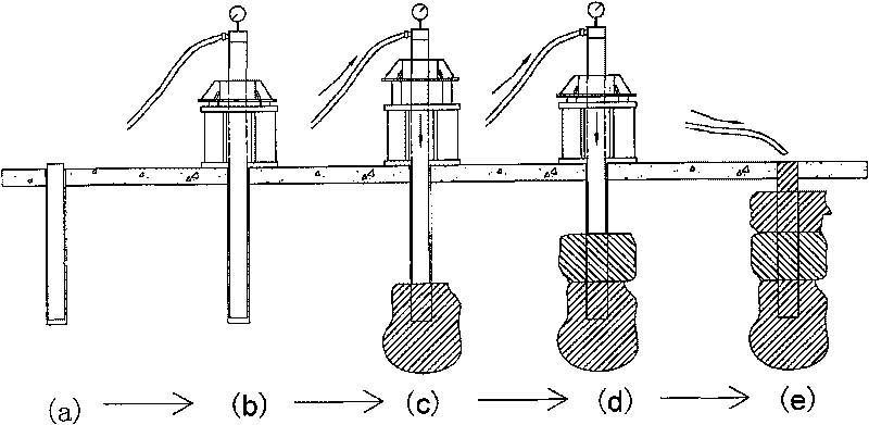
[0047] Such as image 3 Shown, casing grouting method of the present invention is to implement by following specific construction steps:

[0048] 1. Drilling of follow pipe and laying of wall casing. Such as image 3 As shown in (a), before grouting, drill holes to the designed hole depth (30m) by using the pipe drilling method. The drilling machine is a bolter drill equipped with an impactor and a percussion drill bit with eccentric or concentric pipe drilling. Drilling, the bore hole diameter is Φ146 (mm), when drilling, the drill bit drives the wall protection casing 7 into the hole, after the final hole, the drill bit and the drill pipe are taken out, and the wall protection casing 7 is left in the hole; the wall protection casing 7 is formed by The multi-section pipes are connected by threads, and the drill pipe is also made of multi-section pipes through threaded connections. The length of each section matches the length of the sub-rods. Afterwards, connect a joint su...


PUM


Abstract

The invention discloses a casing pipe grouting method and a grouting device thereof. The casing pipe grouting method comprises the following steps in sequence: follow-down drilling, the embedding of the protection casing pipe, the assembling of the grouting device, the grouting of the bottom hole section, the first pulling of the protection casing pipe, the grouting of the initial section of an overburden layer, the grouting of the continues section of the overburden layer and the backfilling of a hole top. The grouting device comprises a screw pump, a mortar feeding pipe, a connecting casingpipe, a protection casing pipe and a pipe extractor. The connecting casing pipe in the position of the hole top is sleeved in the pipe extractor along the power direction, the top part of the protection casing pipe is connected with one end of the connecting casing pipe, a sealing endshield with a pressure gauge is installed at the other end of the connecting casing pipe, a projecting pipe head isarranged on one side of the sealing endshield, the projecting pipe head is connected with one end of the mortar feeding pipe, and the other end of the mortar feeding pipe is connected with the screwpump. The method integrates the advantages of the prior construction methods, and avoids the disadvantages, guarantees the grouting quality, simplifies the grouting process steps, ensures the construction progress, and provides a new approach for the grouting in a loose overburden.

Description

technical field [0001] The invention relates to a construction method for grouting in loose soil and rock layers, in particular to a grouting construction method and a grouting device using a protective wall casing as a grouting pipe. Background technique [0002] At present, in water conservancy and hydropower projects, for the foundation treatment of the overburden (base anti-seepage or foundation consolidation), the orifice sealing grouting method, the drill pipe grouting method and the grouting pipe grouting method in the casing are mainly used. The characteristics are as follows: [0003] (1) The orifice sealing grouting method refers to the construction method of drilling a hole in the overburden layer to the actual depth (generally about 3m), then burying the orifice pipe, and then grouting in sections from top to bottom (drilling one section and grouting one section) . The grouting method is to set the orifice sealer above the orifice pipe, and use the drill pipe a...

Claims


Application Information

Patent Timeline
Patent Type & Authority Patents(China)
IPC IPC(8): E02D15/04
Inventor 邓文明林修建涂怀健何培章姜命强何庚生赵志红任朗明唐存军贺毅吴晓慧
Owner SINOHYDRO BUREAU 8 CO LTD
Learn More