Sensor linear correction method and device
A linear correction, sensor technology, applied in the direction of instruments, etc., can solve the problems of reduced measurement system accuracy, low measurement accuracy and stability of the measurement system, etc., to achieve the effect of improving accuracy, improving test accuracy and stability
- Summary
- Abstract
- Description
- Claims
- Application Information
AI Technical Summary
Problems solved by technology
Method used
Image
Examples
Embodiment 1
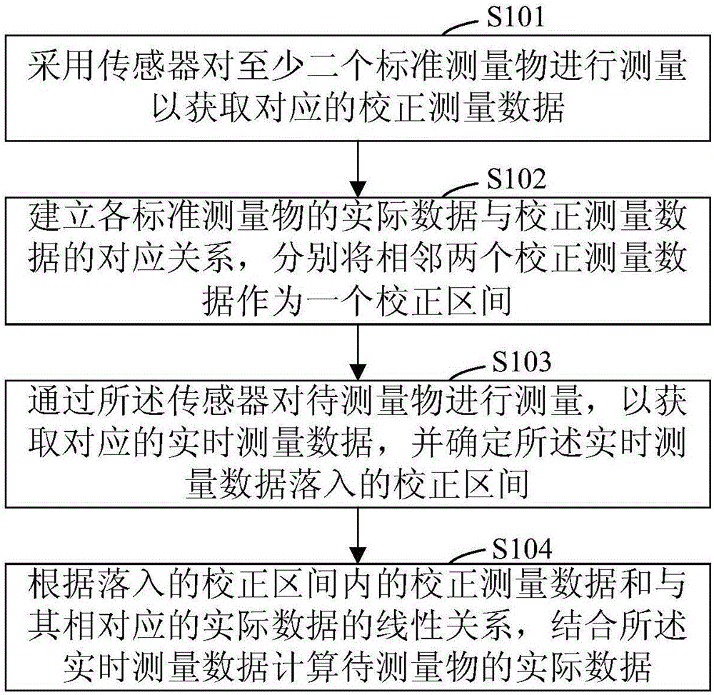
[0047] figure 1 It is a flow chart of a sensor linearity calibration method provided by Embodiment 1 of the present invention. This embodiment is applicable to the situation where a linear sensor needs to be calibrated. This method can be executed by a sensor linearity calibration device, which can be implemented by hardware and / or or software, for example, it may be a control component or a control program integrated in the measurement system. Such as figure 1 As shown, the method specifically includes the following steps:
[0048] Step S101 , using a sensor to measure at least two standard measuring objects, so as to obtain corresponding calibration measurement data.
[0049] Among them, the thickness sensor in the banknote detector is taken as an example to illustrate, and the thickness is respectively from small to large in order of x 1 , x 2 ,...,x n At least two pieces of standard paper pass through the banknote detector, and then the corresponding at least three ca...
Embodiment 2
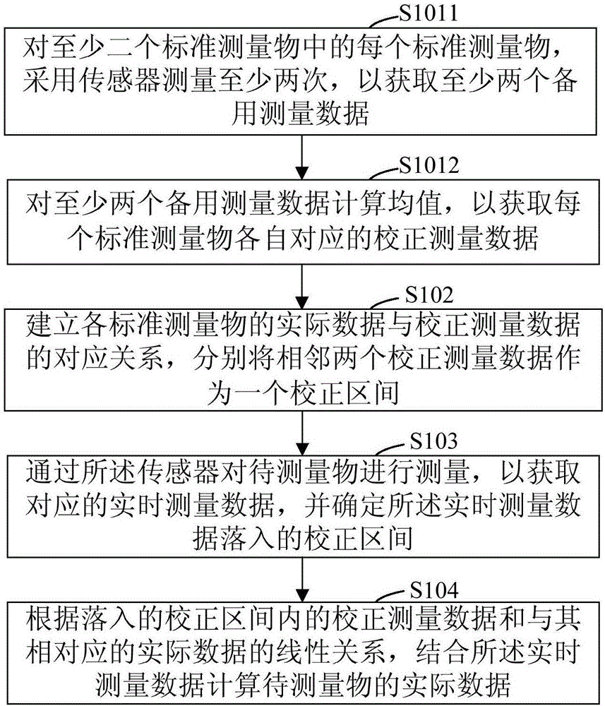
[0068] Please refer to figure 2 , figure 2 It is a flow chart of a sensor linearity correction method provided by Embodiment 2 of the present invention. This embodiment is optimized and improved based on the solutions of the above embodiments, and in particular, a specific solution for obtaining calibration measurement data is provided. Such as figure 2 As shown, the method includes:
[0069] Step S1011 , for each of the at least two standard measuring objects, use the sensor to measure at least twice, so as to obtain at least two spare measurement data corresponding to each standard measuring object.
[0070] Step S1012, calculating the mean value of the at least two spare measurement data, so as to obtain the calibration measurement data corresponding to each standard measurement object.
[0071] Among them, the correction measurement data is obtained by collecting the measurement data corresponding to the sensor and each standard measurement object multiple times and...
Embodiment 3
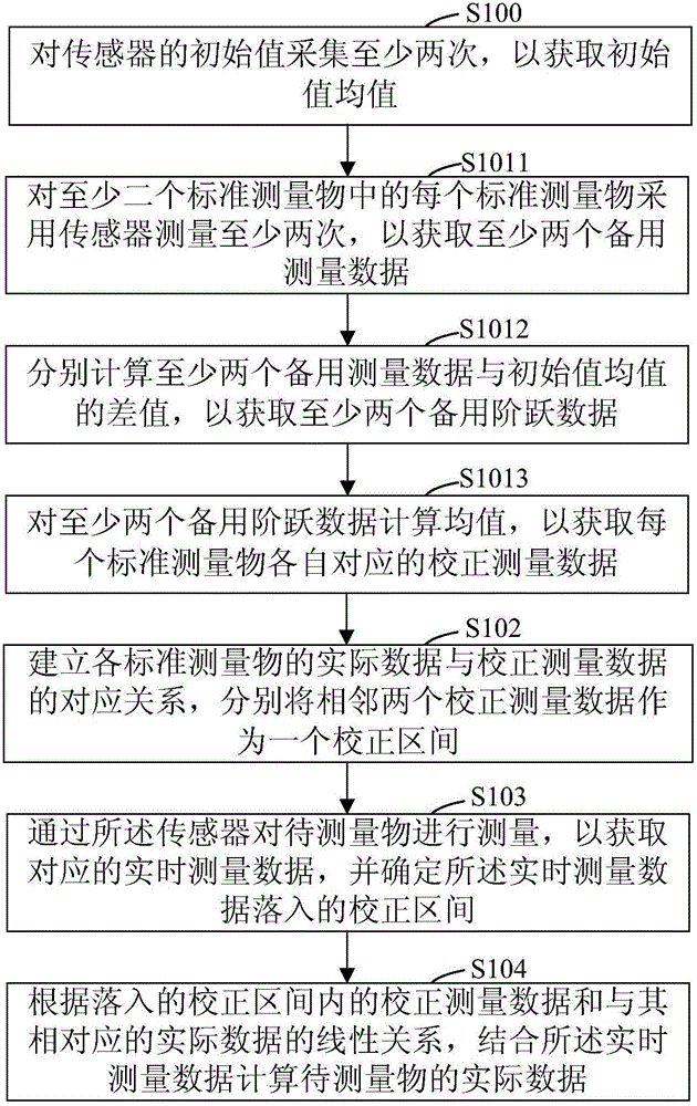
[0077] Please refer to image 3 , image 3 It is a flow chart of a sensor linearity correction method provided by Embodiment 3 of the present invention. This embodiment is based on the solution of the first embodiment above, and optimization and improvement are carried out, and in particular, a specific solution for obtaining calibration measurement data is provided. Such as image 3 As shown, the method includes:
[0078] Step S100, collect the initial value of the sensor at least twice, so as to obtain the average value of the initial value.
[0079] Among them, when the sensor has no input, the initial value of the sensor output is collected multiple times to obtain the average value of the initial value
[0080] Step S1011 , for each of the at least two standard measuring objects, use the sensor to measure at least twice, so as to obtain at least two spare measurement data corresponding to each standard measuring object.
[0081] Step S1012, respectively calculating...
PUM
 Abstract
Description
Claims
Application Information
 - R&D
- Intellectual Property
- Life Sciences
- Materials
- Tech Scout
- Unparalleled Data Quality
- Higher Quality Content
- 60% Fewer Hallucinations
Browse by: Latest US Patents, China's latest patents, Technical Efficacy Thesaurus, Application Domain, Technology Topic, Popular Technical Reports.
© 2025 PatSnap. All rights reserved.Legal|Privacy policy|Modern Slavery Act Transparency Statement|Sitemap|About US| Contact US: help@patsnap.com


