Target extraction and flat-field correction method for imaging system with large difference in gain

An imaging system and flat-field technology, applied in the field of remote sensing imaging, can solve the problems of large gain difference, affecting the uniformity of the sky light source, and inability to apply, and achieve the effect of accurate photometric calibration

Active Publication Date: 2017-06-13
NAT ASTRONOMICAL OBSERVATORIES CHINESE ACAD OF SCI
View PDF9 Cites 3 Cited by
  • Summary
  • Abstract
  • Description
  • Claims
  • Application Information

AI Technical Summary

Problems solved by technology

[0005] There are some limitations in the actual use of the above methods. For example, the sky flat field can be used for visible light. In the infrared band, solar radiation is much weaker than visible light. Infrared is also very sensitive to temperature. The temperature inhomogeneity of the atmosphere along the sky direction will affect the sky. The uniformity of the light source, which affects the measurement accuracy of the sky flat field
Similarly, in the mid-infrared band, it is difficult to ensure the uniformity of the flat field of the dome, because the surrounding objects are all emission sources.
In the vacuum ultraviolet band, the scattering material is not easy to choose, so the method of using a diffuser is difficult to apply
For imaging systems with large gain differences, due to the large gain differences, the observation target can hardly be seen in the original image during observation. The method of moving the sun image needs to know the precise movement amount. Displacement between the can not be calculated, the method can not be applied

Method used


Image

  • Target extraction and flat-field correction method for imaging system with large difference in gain
  • Target extraction and flat-field correction method for imaging system with large difference in gain
  • Target extraction and flat-field correction method for imaging system with large difference in gain

Examples


Embodiment Construction

[0030] In order to make the purpose, technical solutions and advantages of the embodiments of the present invention clearer, the technical solutions in the embodiments of the present invention will be clearly and completely described below in conjunction with the drawings in the embodiments of the present invention. Obviously, the described embodiments It is a part of embodiments of the present invention, but not all embodiments. Based on the embodiments of the present invention, all other embodiments obtained by persons of ordinary skill in the art without making creative efforts belong to the protection scope of the present invention.

[0031] In order to facilitate the understanding of the embodiments of the present invention, the technical solution of the present invention will be further described in detail below with reference to the drawings and embodiments.

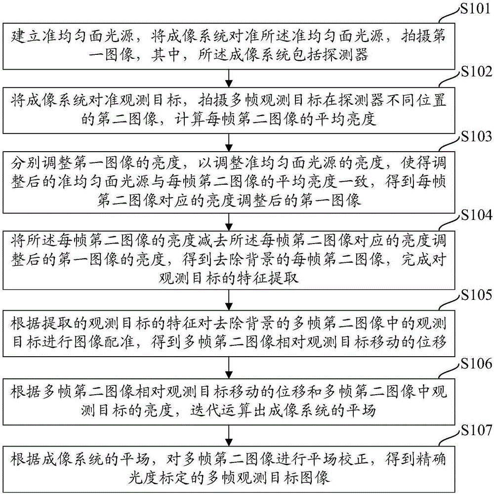
[0032] figure 1 It is a schematic flowchart of a target extraction method for an imaging system with a large g...


PUM


Abstract

An embodiment of the invention relates to a target extraction and flat-field correction method for imaging system with large difference in gain. The target extraction and flat-field correction method is designed for that the imaging system of larger difference cannot recognize current situation of an observed object in an original observed image. The method comprises the steps of establishing a certain uniform face light source system and shooting a light source image; acquiring images that the multi-frame observed target is in different place; utilizing the certain uniform face light source to deduct uneven background of each frame observed image and extracting feature information of the observed object; rectifying the image sequencing in different places of a detector based on obtained features of the observed object; utilizing a fundamental principle that an intensity ratio of the observed object in different places of the detector is equal to a gain ration in different places to iterate the flat field; utilizing the flat field image of iteration to carry out the flat field correction to the observed target image so as to complete calibration of accurate luminosity of the observed object.

Description

technical field [0001] The invention relates to the field of remote sensing imaging, including remote sensing imaging of ground or astronomical targets, in particular to a target extraction and flat field correction method for imaging systems with large gain differences. Background technique [0002] In the field of remote sensing observation, such as space-to-Earth observation or space and ground-based astronomical observation, telescopes are used to observe wavelengths such as soft X-rays, ultraviolet, visible light, and infrared, and the observation images are finally recorded on the detector. Generally, the detector can use a charge-coupled device (Charge-Coupled Device, CCD) or a complementary metal oxide semiconductor device (Complementary Metal Oxide Semiconductor, CMOS) camera. In the visible light band, CCD or CMOS cameras generally have little difference in the gain of different pixels. When the telescope system basically has no vignetting, the target can be easily...

Claims


Application Information

Patent Timeline
Patent Type & Authority Applications(China)
IPC IPC(8): G01J1/42
CPCG01J1/4228
Inventor 白先勇冯志伟张志勇邓元勇杨潇张洋
Owner NAT ASTRONOMICAL OBSERVATORIES CHINESE ACAD OF SCI
Why Eureka
Try Eureka