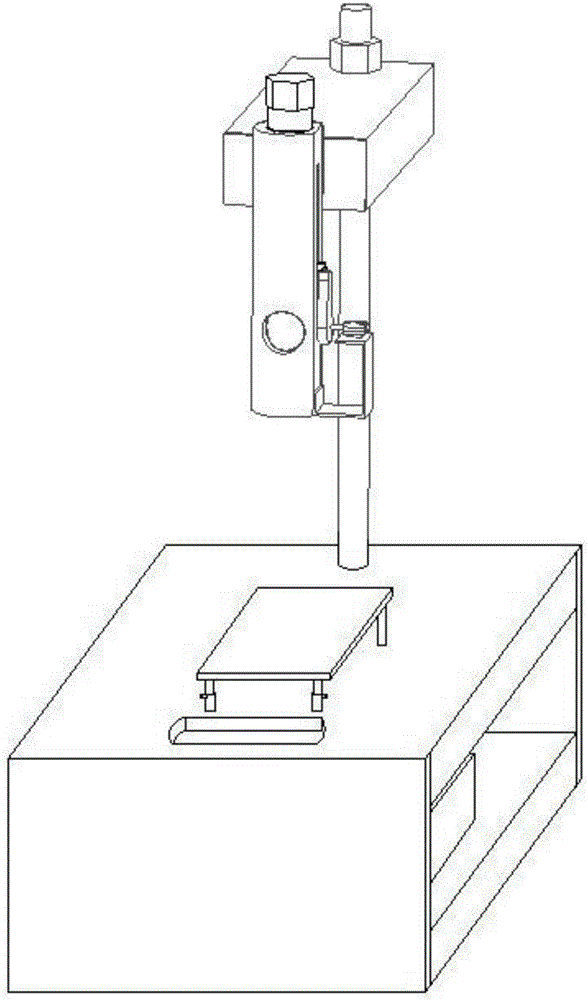
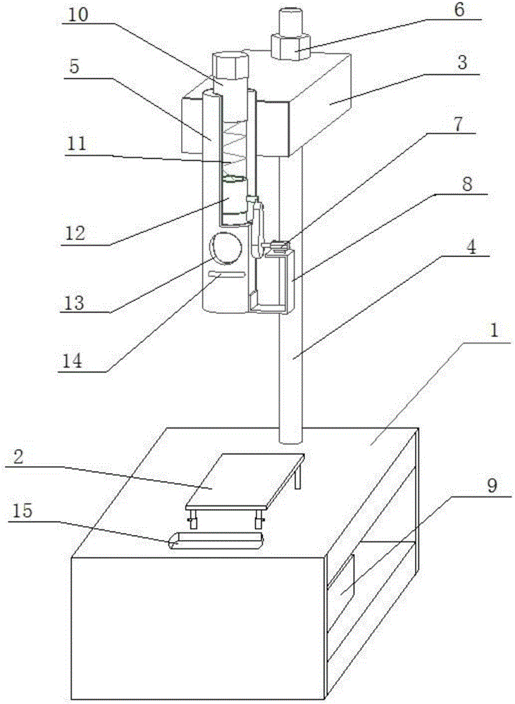
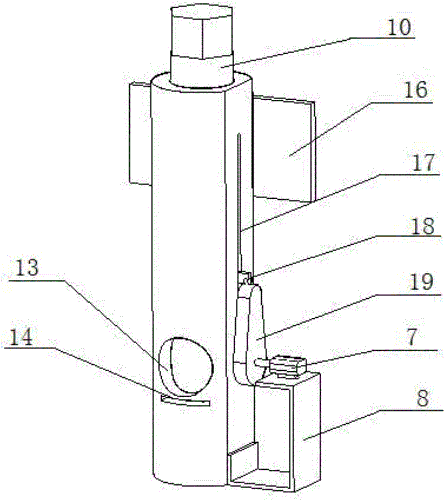
Automatic falling ball experiment device

An experimental device and automatic technology, applied in the field of testing, can solve problems such as lack of solutions, large overall structure, increased labor intensity, etc., and achieve the effect of small and compact overall structure, convenient operation, and compact structure

Pending Publication Date: 2017-06-13
吕心怡
View PDF9 Cites 6 Cited by
  • Summary
  • Abstract
  • Description
  • Claims
  • Application Information

AI Technical Summary

Problems solved by technology

It is impossible to conduct the falling ball test on the product only once, which exposes the disadvantages of manual falling ball test: repeated experiments are labor-intensive and low in efficiency
[0003] At present, there are also many automatic ball-dropping devices, but these automatic ball-dropping devices are free-falling motions of the ball, that is, the initial velocity of the ball is zero. Moreover, the impact force of the ball on the experimental sample can only be adjusted by the quality and height of the ball, which will increase the number of experiments and increase the labor intensity from the side
[0004] To sum up, there is still no effective solution to the problem of how to reduce the size of the device structure and make the impact force of the falling ball arbitrarily adjustable in the automatic falling ball experiment in the prior art

Method used


Image

  • Automatic falling ball experiment device
  • Automatic falling ball experiment device
  • Automatic falling ball experiment device

Examples


Embodiment Construction

[0030] It should be pointed out that the following detailed description is exemplary and intended to provide further explanation to the present application. Unless defined otherwise, all technical and scientific terms used herein have the same meaning as commonly understood by one of ordinary skill in the art to which this application belongs.

[0031] It should be noted that the terminology used here is only for describing specific implementations, and is not intended to limit the exemplary implementations according to the present application. As used herein, unless the context clearly dictates otherwise, the singular is intended to include the plural, and it should also be understood that when the terms "comprising" and / or "comprising" are used in this specification, they mean There are features, steps, operations, means, components and / or combinations thereof.

[0032] As introduced in the background technology, there are disadvantages in the prior art that the falling bal...


PUM


Abstract

The invention discloses an automatic falling ball experiment device, and aims at solving the problems that a falling ball device is relatively large in volume and the falling ball impact force cannot be freely adjusted in the prior art. The automatic falling ball experiment device has the effects that the structure is compact, the impact force on a sample can be freely adjusted, and balls can be automatically recovered after an experiment. According to the technical scheme, the automatic falling ball experiment device comprises an experiment table, an elevator mechanism, a falling ball tube and a storage box, wherein the inside of the experiment table is of a hollow structure; the elevator mechanism comprises an adjusting block, a screw and a screw drive mechanism; a bolt is arranged at the top of the falling ball tube and is connected with a guide block through a spring; a guide groove is formed in the side surface of the falling ball tube; and the guide block is controlled to slide by a cam mechanism along the guide groove.

Description

technical field [0001] The invention relates to the testing field, in particular to an automatic ball drop test device. Background technique [0002] Many products, such as electronic products, need to undergo a ball drop test to test their impact resistance before they are put on the market, so the ball drop test plays an important part in product testing. It is impossible to conduct the falling ball test on the product only once, which exposes the disadvantages of manual falling ball test: repeated experiments are labor-intensive and low in efficiency. [0003] At present, there are also many automatic ball-dropping devices, but these automatic ball-dropping devices are free-falling motions of the ball, that is, the initial velocity of the ball is zero. Moreover, the impact force of the ball on the experimental sample can only be adjusted by the quality and height of the ball, which will increase the number of experiments and increase the labor intensity from the side. ...

Claims


Application Information

Patent Timeline
Patent Type & Authority Applications(China)
IPC IPC(8): G01M7/08
CPCG01M7/08
Inventor 吕心怡
Owner 吕心怡
Why Eureka
Try Eureka