Eureka AIR delivers breakthrough ideas for toughest innovation challenges, trusted by R&D personnel around the world.

Head-mounted display device and display method thereof

A head-mounted display and display device technology, applied in the wearable field, can solve problems such as complex optical systems and poor performance of augmented reality devices

Pending Publication Date: 2017-06-13
BEIJING 7INVENSUN TECH
View PDF8 Cites 4 Cited by
  • Summary
  • Abstract
  • Description
  • Claims
  • Application Information

AI Technical Summary

Problems solved by technology

[0003] The current augmented reality devices usually use smaller display screens. In order to achieve the same exit pupil size, the design difficulty of the optical system is greatly increased. Therefore, the performance of the current augmented reality devices is poor, or the optical system is very complicated.

Method used


Image

  • Head-mounted display device and display method thereof
  • Head-mounted display device and display method thereof
  • Head-mounted display device and display method thereof

Examples


Embodiment 1

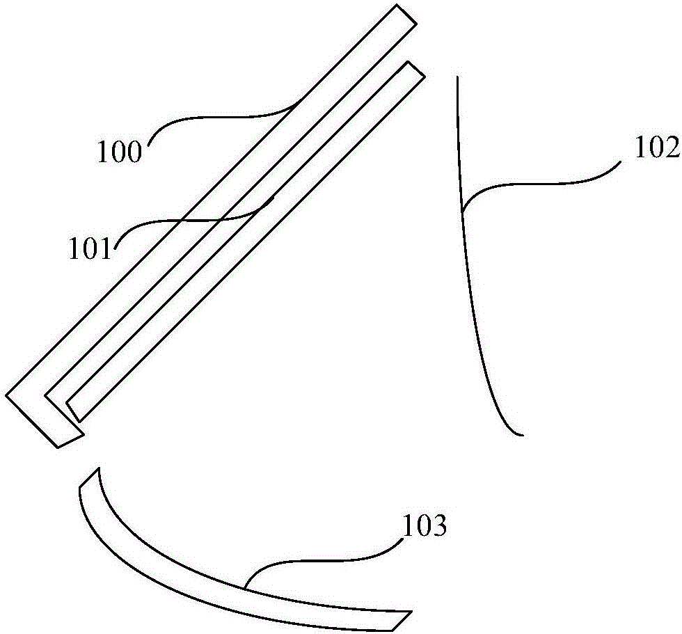
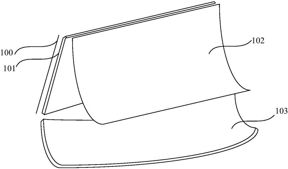
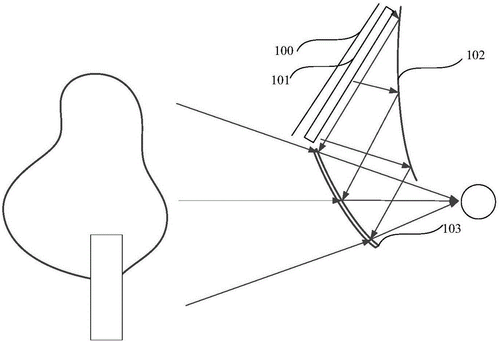
[0037] Embodiment 1 of the present invention proposes a head-mounted display device, such as figure 1 Shown is a side view of the head-mounted display device, figure 2It is a front view of a head-mounted display device, including a carrying device 100, a first optical module 102 and a second optical module 103, wherein the carrying device 100 is used to carry a display device 101, wherein the first optical module 102 is located on the carrying device The front of the display device 101 carried by the 100 is at a certain angle to the display device 101, and the second optical module 103 is located below the display device 101 and at a certain angle to the display device 101;

[0038] The first optical module 102 is configured to reflect the image displayed by the display device 101 to the second optical module 103;

[0039] The second optical module 103 is configured to reflect the image of the first optical module 102 to a preset position to form a first image, and transmit ...

Embodiment 2

[0071] Embodiment 2 of the present invention proposes a display method for a head-mounted display device, where the head-mounted display device is any head-mounted display device proposed in Embodiment 1. The flow of the display method is as follows, see Figure 10 :

[0072] Step 21, placing the display device on the carrying device;

[0073] Step 22, adjusting the carrying device and the first optical module so that the first optical module reflects the image displayed on the display device on the carrying device to the second optical module;

[0074] Step 23, adjust the second optical module so that the second optical module reflects the first optically reflected image to a preset position to form a first image, and transmits the image of the real object other than the head-mounted display device to a preset position. The second image is formed at a position such that the second image is superimposed with the first image at a preset position.

[0075]Based on the above a...


PUM


Abstract

The invention provides a head-mounted display device and a display method thereof. The device comprises a carrying device, a first optical module and a second optical module, the first optical module is located in front of a display device carried by the carrying device and forms a certain angle with the display device, the second optical module is located below the display device and forms a certain angle with the display device; the carrying device is used for carrying the display device; the first optical module is used for reflecting the image displayed by the displayed device to the second optical module; the second optical module is used for reflecting the image of the first optical module to a preset position to form a first image, and transmits the images of real objects outside the head-mounted display device to a preset position to form a second image, the second image is superimposed with the first image. The reality augmentation device composed of the display device, the first optical module and the second optical module is larger in view field, and simple in optical system.

Description

technical field [0001] The present invention relates to the field of wearable technology, in particular to a head-mounted display device and a display method thereof. Background technique [0002] Augmented Reality (Augmented Reality, AR) is a technology that integrates real world and virtual world information. It can calculate the position and angle of camera images in real time and add corresponding images. The interaction between the virtual world and the real world has become one of the research hotspots of many well-known universities and research institutions at home and abroad in recent years because of its wide application fields. [0003] Current augmented reality devices usually use smaller display screens. In order to achieve the same exit pupil size, the design difficulty of the optical system is greatly increased. Therefore, the performance of the current augmented reality devices is poor, or the optical system is very complicated. Contents of the invention ...

Claims


Application Information

Patent Timeline
Patent Type & Authority Applications(China)
IPC IPC(8): G02B27/01
CPCG02B27/0172
Inventor 黄通兵肖冰
Owner BEIJING 7INVENSUN TECH
Why Eureka
Eureka Blog
Learn More