
Display device

A technology for a display device and a display panel, which is applied to static indicators, instruments, etc., and can solve problems such as damage to the driver chip 20, impact on service life, and abnormal display of a liquid crystal display device, achieving the effect of normal display and improved reliability

Active Publication Date: 2017-06-13
KUSN INFOVISION OPTOELECTRONICS
View PDF5 Cites 12 Cited by
  • Summary
  • Abstract
  • Description
  • Claims
  • Application Information

AI Technical Summary

Problems solved by technology

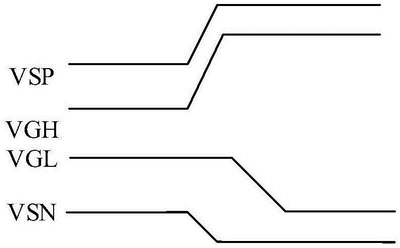
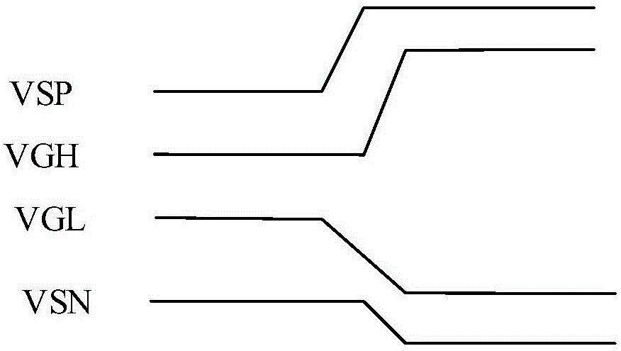
As mentioned above, the power-on sequence provided by the power supply chip 30 does not match the required power-on sequence of the driver chip 20, resulting in abnormal display of the liquid crystal display device, and even damage to the driver chip 20, which affects the service life.

Method used


Image

  • Display device
  • Display device
  • Display device

Examples


Embodiment Construction

[0029] Hereinafter, various embodiments of the present invention will be described in more detail with reference to the accompanying drawings. In the various drawings, the same elements are represented by the same or similar reference numerals. For the sake of clarity, the various parts in the drawings are not drawn to scale.

[0030] The present invention can be presented in various forms, some examples of which will be described below.

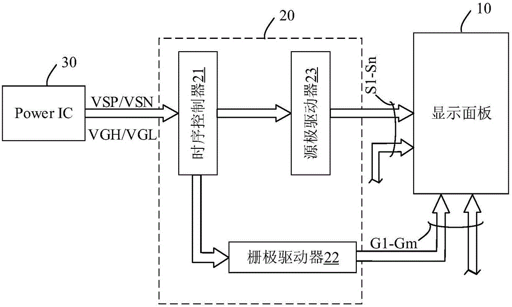
[0031] image 3 It shows a schematic block diagram of a display device according to an embodiment of the present invention. Such as image 3 As shown, the display device includes a display panel 10, a driving chip 20, a power supply chip 30, and a first timing adjustment circuit 40.

[0032] The display panel 10 has a plurality of gate lines G1-Gm and a plurality of data lines S1-Sn crossing each other, and a plurality of pixels formed at intersections of the gate lines G1-Gm and the data lines S1-Sn.

[0033] The power chip 30 provides a power su...


PUM


Abstract

The present invention discloses a display device. The device comprises: a display panel; a power supply chip connected with the display panel and configured to provide supply voltage for the display panel to generate a first set of time series signals; a driving chip configured to generate grid selection signals and gray-scale signals according to a second set of time series signals to drive the display panel to display an image; and a first time series regulation circuit connected between the driving chip and the power supply chip and configured to convert the first set of time series signals to the second set of time series signals. The display device provided by the invention converts the first set of time series signals provided by the power supply chip to the second set of time series signals required by the driving chip through the first time series regulation circuit so as to avoid the problem that time series provided by the power supply chip is not matched with the time series required by the driving chip to cause that a liquid-crystal display device cannot normally display.

Description

Technical field [0001] The present invention belongs to the technical field of displays, and more specifically, relates to a display device. Background technique [0002] Since liquid crystal display devices have the advantages of lightness, thinness, energy saving, and low power consumption, they have been widely used in electronic equipment such as televisions, computers, mobile phones, and digital cameras. [0003] figure 1 A schematic block diagram of a display device according to the related art is shown. Such as figure 1 As shown, the display device includes a display panel 10, a driver IC (Driver IC) 20, and a power IC (Power IC) 30. Although the display panel 10 is not particularly illustrated, a plurality of pixels are arranged in a matrix on a glass substrate, and each pixel has a thin film transistor and a liquid crystal element connected in series. A common potential Vcom is applied to the liquid crystal element of each pixel. The selection terminals of the thin film...

Claims


Application Information

Patent Timeline
IPC IPC(8): G09G3/36
CPCG09G3/3677
Inventor 王铮卢佳惠
Owner KUSN INFOVISION OPTOELECTRONICS
Learn More