
A method for replacing the ei-type laminated silicon steel core transformer with a ring-type power transformer

A technology of power transformers and silicon steel cores, which is applied in the manufacture of inductors/transformers/magnets, transformer/inductor cores, transformer/inductor components, etc., can solve problems such as high cost, potential safety hazards, waste of resources, etc., and achieve Reduce costs, reduce manufacturing costs, and contribute to environmental protection

Active Publication Date: 2018-06-05
青州市宝利电子有限公司
View PDF6 Cites 0 Cited by
  • Summary
  • Abstract
  • Description
  • Claims
  • Application Information

AI Technical Summary

Problems solved by technology

However, the toroidal power transformer has a fatal flaw: high cost
However, this method can only protect once, and at the same time, because the thermal fuse adopts the principle of thermal fusing, when the fuse is blown, the entire transformer is scrapped, resulting in a great waste of resources
[0011] In addition, when the transformer has multiple secondary windings, some of the secondary windings account for a small proportion of the total power. Even if these small windings fail and burn out, they cannot be fed back to the primary to activate the thermal fuse, and the safety hazard still exists.

Method used


Image

  • A method for replacing the ei-type laminated silicon steel core transformer with a ring-type power transformer
  • A method for replacing the ei-type laminated silicon steel core transformer with a ring-type power transformer
  • A method for replacing the ei-type laminated silicon steel core transformer with a ring-type power transformer

Examples


Embodiment Construction

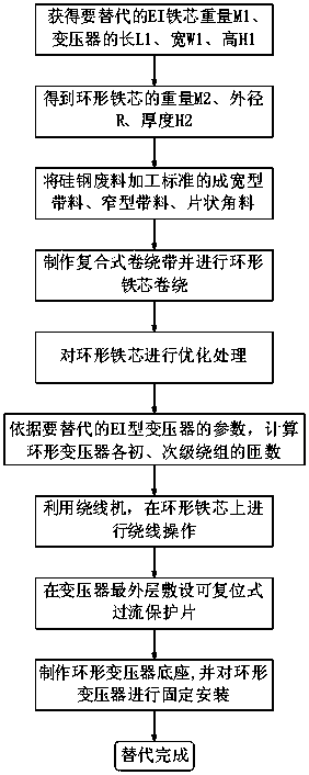
[0063] Referring to the accompanying drawings, the method for replacing the EI-type laminated silicon-steel core transformer by the toroidal power transformer of the present invention includes the following 10 steps, which will be analyzed in detail below.

[0064] Step 1), take the EI-type laminated silicon-steel core transformer to be replaced, obtain its core weight M1, and measure the length L1, width W1, and height H1 of the transformer.

[0065] Step 2), obtain the toroidal core parameters of the toroidal power transformer, the weight of the toroidal core M2= M1*(70±5)%, the outer diameter of the toroidal core R≤L1 and R≤L1, the thickness of the toroidal core H2≤H1 . Under the condition of equal power, the ring-type iron core replaces the EI-type iron core. Since the weight is reduced by 30%, the specific gravity of the two types of iron cores is the same, so the volume is smaller than the EI-type iron core. The diameter of the aluminum-clad enameled wire replacing the ...


PUM

PropertyMeasurementUnit
thicknessaaaaaaaaaa

Abstract

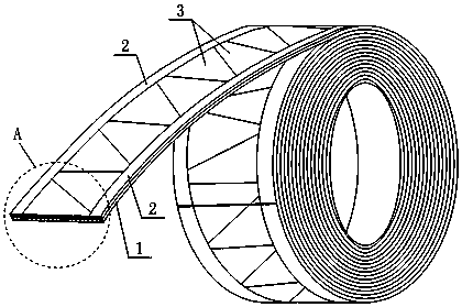
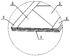
The invention relates to a method replacing an EI type laminated silicon steel iron core transformer with an annular type power transformer and the annular type power transformer. The replacing method mainly comprises the steps of obtaining the weight, length, width and height of an iron core of the EI type transformer; obtaining the weight, external diameter and thickness of an annular iron core; processing a silicon steel waste material into a wide type belt material, a narrow type belt material and a piece-shaped angle material; manufacturing a compound winding belt and winding the annular iron core; calculating the number of turns of each primary coil of the annular type transformer, and conducting winding operation on the annular iron core; manufacturing and mounting an annular type transformer base. The method replacing the EI type laminated silicon steel iron core transformer with the annular type power transformer is simple in procedure, convenient to operate and conducive to environmental protection and popularization of the annular type transformer, can recycle discarded resources, and improve the transformer performance and lower the cost. In the annular type power transformer, the discarded resources are utilized to manufacture the iron core, a self-recovery overcurrent protection sheet is installed in the transformer, the resources are saved, and the transformer performance is improved.

Description

technical field [0001] The invention relates to the field of transformer production and processing, in particular to a method for a ring-shaped power transformer to replace an EI-type laminated silicon-steel core transformer and a ring-shaped power transformer. Background technique [0002] As we all know, the toroidal power transformer has the advantages of high conversion efficiency, low temperature rise, small interference and flexible design compared with the EI type laminated silicon steel core transformer. However, the toroidal power transformer has a fatal flaw: high cost. [0003] The iron core used to wind the toroidal transformer is the toroidal core, which is an important reason for the high cost of the transformer. The existing annular iron core is generally made of cold-rolled grain-oriented silicon steel sheet (the thickness of the sheet is generally less than 0.35mm), and the whole strip is rolled along the "orientation" direction, and then heat-treated and i...

Claims


Application Information

Patent Timeline
Patent Type & Authority Patents(China)
IPC IPC(8): H01F27/25H01F27/28H01F27/32H01F27/40H01F41/02
CPCH01F27/25H01F27/2823H01F27/2895H01F27/324H01F27/402H01F41/0213H01F2027/406
Inventor 张立宝刘国平
Owner 青州市宝利电子有限公司
Learn More