A Microstrip Double-g Narrowband Bandpass Filter

A band-pass filter and filter technology, applied in waveguide-type devices, resonators, circuits, etc., can solve the problems of poor squareness, insufficient out-of-band suppression, and large insertion loss, avoiding installation and reducing size. , to avoid the effect of the debugging process

Inactive Publication Date: 2019-06-14
UNIV OF ELECTRONICS SCI & TECH OF CHINA
View PDF6 Cites 0 Cited by
  • Summary
  • Abstract
  • Description
  • Claims
  • Application Information

AI Technical Summary

Problems solved by technology

[0005] Aiming at the deficiencies of the prior art, the present invention proposes a miniaturized high-performance narrowband bandpass filter, which innovatively adopts a double G-type centrosymmetric microstrip structure to solve the problem of traditional narrowband bandpass filter transmission When the insertion loss is large, the out-of-band suppression is not high enough, and the squareness coefficient is poor

Method used


Image

  • A Microstrip Double-g Narrowband Bandpass Filter
  • A Microstrip Double-g Narrowband Bandpass Filter
  • A Microstrip Double-g Narrowband Bandpass Filter

Examples


Embodiment Construction

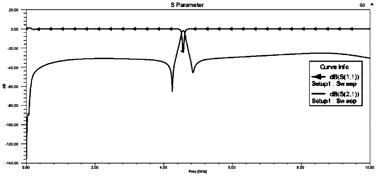
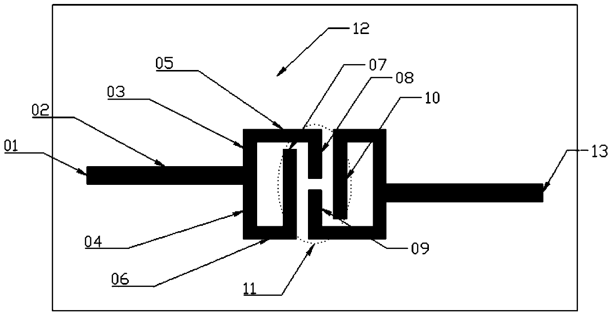
[0011] The present invention is a dual G-type narrowband bandpass filter, which includes two G-type resonant structures composed of multiple meandering lines with central symmetry, one input microstrip transmission line, one output microstrip transmission line, and the substrate is Rogers RO4350. It is characterized in that two multi-zigzag asymmetric G-type resonator units are arranged symmetrically in the center, which realizes the hybrid coupling of electric and magnetic fields around the center point, effectively reduces the volume of the resonator, and widens the range of suppressing sidebands. A narrow band pass filter with ultra-wide and ultra-flat out-of-band suppression is realized.

[0012] Specific design methods such as figure 1 Shown is a schematic diagram of the structure of the present invention, and the filter is placed on the substrate 12. The signal is input by input terminal 01 (13), output by 13 (01), and 03~08 form a multi-zigzag G-type resonant unit. The tw...


PUM


Abstract

The invention discloses a microstrip double-G narrowband bandpass filter, which belongs to the technical field of microwave engineering, in particular to the field of narrowband bandpass filters. Through two multi-meander asymmetric G-shaped resonator units arranged symmetrically in the center, the hybrid coupling of the electric field and magnetic field around the center point is realized, the volume of the resonator is effectively reduced, the range of sideband suppression is broadened, and the band An ultra-wide and ultra-flat narrow bandpass filter with outer rejection. By adopting the electromagnetic hybrid coupling method between the two resonant units, the separate design of magnetic coupling and electrical coupling is avoided, the size of the filter is effectively reduced, and the bandwidth is controlled. Ultra-wide out-of-band rejection is achieved using an asymmetrically coupled resonant cell model. Adopting the form of microstrip avoids the complex debugging process such as cavity filter processing. In PCB integrated circuits, it can be molded with the substrate at one time, avoiding the installation and welding process.

Description

Technical field [0001] The invention belongs to the field of microwave engineering technology, especially the field of narrowband bandpass filters. Background technique [0002] With the rapid development of radar, precision guidance, remote sensing and radio communication industries, the need for miniaturized, high-performance narrow-band bandpass filters has become more and more urgent. Among various circuit structures, the microstrip line structure is widely used due to its advantages of simple processing, debugging-free, low cost, and easy integration. Therefore, the narrowband bandpass filter of the microstrip structure has always been the focus and hot spot in the field of wireless communication. The traditional microstrip open loop resonant structure filter has problems such as large volume, large insertion loss, poor rectangular coefficient, difficult integration, and mutual interference between adjacent passbands. [0003] J.S.Hong and M.J.Lancaster proposed a microstrip...

Claims


Application Information

Patent Timeline
Patent Type & Authority Patents(China)
IPC IPC(8): H01P1/20H01P1/203H01P7/08
CPCH01P1/20H01P1/203H01P7/08H01P7/088
Inventor 邹焕马睿徐腾飞吴绍炜
Owner UNIV OF ELECTRONICS SCI & TECH OF CHINA
Why Eureka
Try Eureka