Connector and locking sleeve thereof

A technology of connectors and locking sleeves, which is applied in the direction of connection, parts of connection devices, electrical components, etc., can solve the problem of forced separation of connectors, etc., and achieve simple and convenient design, strong versatility, and increased radial distance Effect

Inactive Publication Date: 2017-06-13
CHINA AVIATION OPTICAL-ELECTRICAL TECH CO LTD
View PDF4 Cites 5 Cited by
  • Summary
  • Abstract
  • Description
  • Claims
  • Application Information

AI Technical Summary

Problems solved by technology

[0005] During the actual use of the above-mentioned socket connector, the steel ball lock between the plug connector 1 and the socket connector 2 can only be released by applying force to the locking sleeve to realize the separation of the two. When an abnormal situation occurs, only Applying force to the cable or cable clamp connected to the connector cannot force the connector to separate under abnormal conditions

Method used


Image

  • Connector and locking sleeve thereof
  • Connector and locking sleeve thereof
  • Connector and locking sleeve thereof

Examples


Embodiment Construction

[0022] Embodiments of the present invention will be further described below in conjunction with the accompanying drawings.

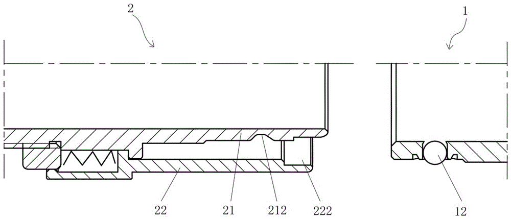
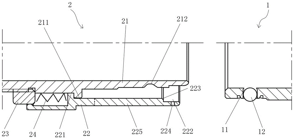
[0023] The specific structure of the push-pull connector assembly is as follows: Figure 2 to Figure 4 As shown, a plug connector 1 and a socket connector 2 are included, and the socket connector 2 constitutes a specific embodiment of the connector of the present invention.

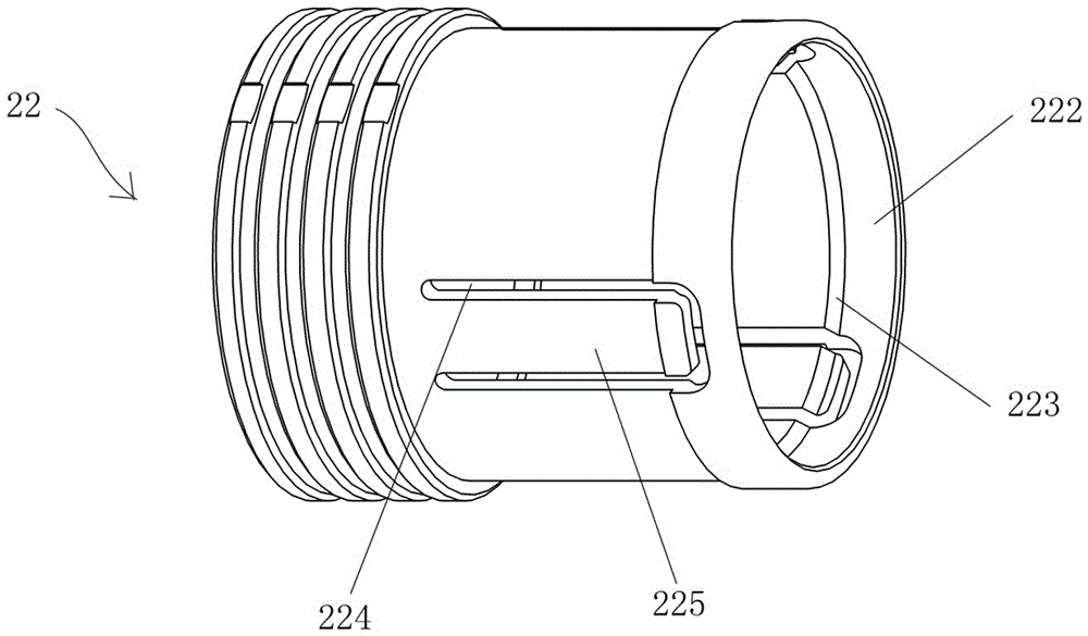
[0024] The socket connector 2 includes an inner housing 21 and a locking sleeve 22 fitted outside the inner housing 21 . The gap between the inner housing 21 and the locking sleeve 22 constitutes an insertion space for the plug connector 1 to be inserted into. The outer periphery of the inner casing 21 is provided with a first annular boss 211, and the locking sleeve 22 includes a sleeve body. A second annular boss 221 is arranged on the inner peripheral surface of the sleeve body. The side wall surface and the left side wall surface of the first annular boss 211 block and coopera...


PUM


Abstract

The invention relates to a connector and a locking sleeve thereof. The connector includes an inner housing and a locking sleeve set outside the inner housing. A lock for locking steel balls on the adapter connector to enter and lock the steel balls is provided on the outer wall of the inner housing. The locking groove; the locking sleeve includes a sleeve body, and the sleeve body has a steel ball stopper for radially stopping the locking steel ball on the adapter connector in the locking groove. The ball stop part is composed of an elastic structure that can elastically deform in the radial direction when the adapter connector is subjected to a forced pulling force, and then make way for the locking steel ball in the radial direction to realize unlocking. In the actual use of the present invention, when an abnormal situation occurs and the cable or cable clamp is directly subjected to separation force but the locking sleeve is not subjected to separation force, the arrangement of the elastic structure on the locking sleeve can release the connection between the connector and the adapter. The steel ball lock between the connectors enables the connector and the mating connector to be separated smoothly and forcibly.

Description

technical field [0001] The invention relates to a connector and a locking sleeve thereof. Background technique [0002] At present, a locking steel ball locking structure is generally used between the plug connector and the socket connector of the push-pull connector assembly, so as to achieve the purpose of fast insertion and stable locking between the plug and the socket. The structure is generally as follows: figure 1 As shown, it includes a plug connector 1 and a receptacle connector 2. The receptacle connector 2 includes an inner housing 21 and a locking sleeve 22 set outside the inner housing 21. The locking sleeve 22 and the inner housing 21 An elastic member 24 that can provide leftward axial thrust to the locking sleeve 22 is disposed therebetween. An inserting space for inserting the plug connector 1 is formed between the inner housing 21 and the locking sleeve 22 . [0003] The plug end of the plug connector 1 is provided with a plurality of locking steel balls ...

Claims


Application Information

Patent Timeline
Patent Type & Authority Applications(China)
IPC IPC(8): H01R13/627
CPCH01R13/6276H01R13/6271
Inventor 王鹏赵聪卞书波
Owner CHINA AVIATION OPTICAL-ELECTRICAL TECH CO LTD
Why Eureka
Try Eureka