Assembly for connecting an adapter shaft to a shaft in a force-fitting manner using a clamping ring

a technology of clamping ring and adapter shaft, which is applied in the direction of rigid shaft couplings, couplings, mechanical devices, etc., can solve the problems of not having an adapter shaft, and achieve the effect of great elasticity

Pending Publication Date: 2020-08-27
SEW-EURODRIVE GMBH & CO KG
View PDF2 Cites 0 Cited by
  • Summary
  • Abstract
  • Description
  • Claims
  • Application Information

AI Technical Summary

Benefits of technology

[0020]According to example embodiments, the shaft is inserted into a region of the adapter shaft that is arranged as a hollow shaft region, and in particular is situated coaxially with the adapter shaft. This has the advantage that the shaft is able to be accommodated in the adapter shaft and in the process is centered with respect to the axis of rotation of the adapter shaft.
[0021]According to example embodiments, the axial slot or the axial slots at the axial end of the adapter shaft lead(s) into the ambient air. This has the advantage that the adapter shaft has great elasticity in the axial end region.
[0022]According to example embodiments, the adapter shaft has an increasing radial distance in the direction of the axial end, in particular has a radially protruding bead that extends in the circumferential direction, so that an engagement of the clamping ring from behind is provided, the adapter shaft thus particularly engaging with the clamping ring from behind. This has the advantage that the clamping ring is able to be snapped onto the adapter shaft because the bead, which is elastically deflected in the radially inward direction, clicks into place behind the clamping ring and thereby secures the clamping ring on the adapter shaft.

Problems solved by technology

This is so because without axial slots, there would be a risk that the adapter shaft does not form any circumferential radially directed, sinusoidal-type characteristics in the circumferential direction when the threaded pin is pressed against the adapter shaft, but the adapter shaft rests against the solid shaft as uniformly as possible.

Method used


Image

  • Assembly for connecting an adapter shaft to a shaft in a force-fitting manner using a clamping ring
  • Assembly for connecting an adapter shaft to a shaft in a force-fitting manner using a clamping ring
  • Assembly for connecting an adapter shaft to a shaft in a force-fitting manner using a clamping ring

Examples


Embodiment Construction

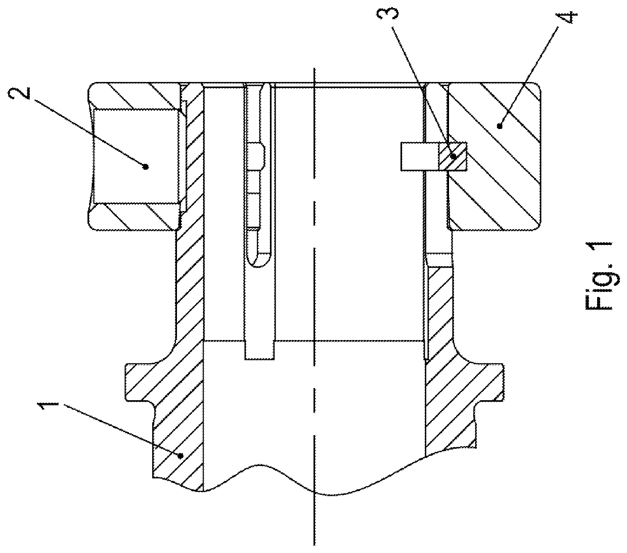
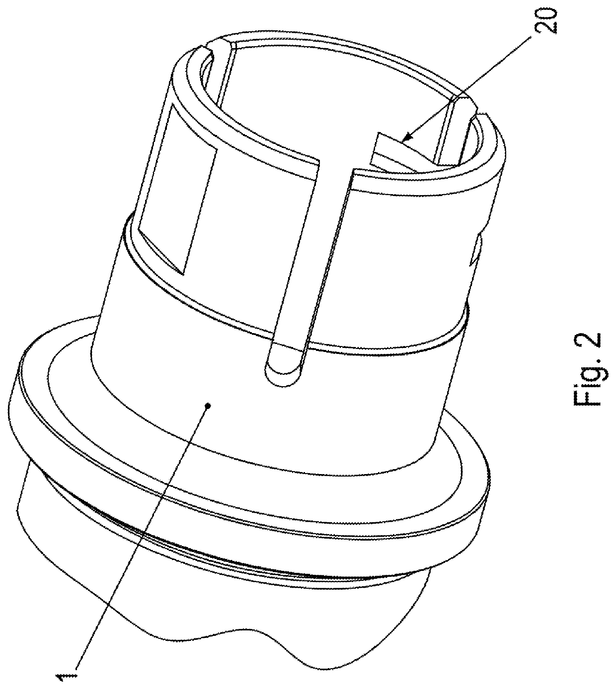
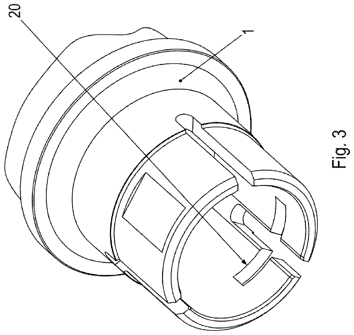
[0039]As illustrated in the FIGS. 1 through 6, adapter shaft 1 has a hollow shaft region provided with axially extending slots, i.e. axial slots. The axial slots are, for example, set apart from one another at regular intervals in the circumferential direction and extend from the axially outer first end region of adapter shaft 1 to an axial position that is situated outside the axial region covered by clamping ring 4. The number of slots is, for example, three.

[0040]A solid shaft is inserted into adapter shaft 1. As a result, this solid shaft is radially surrounded by adapter shaft 1.

[0041]A threaded pin 2 is screwed into a threaded bore that radially extends through clamping ring 4 and exerts pressure on a flattened region 20 provided on adapter shaft 1.

[0042]A flattened region is provided on the outer side of adapter shaft 1 and tangentially aligned with respect to the center axis or the axis of rotation of the adapter shaft.

[0043]Threaded pin 2 exerts pressure on the flattened re...


PUM


Abstract

In an assembly for connecting an adapter shaft to a shaft in a force-fitting manner using a clamping ring, the clamping ring is mounted on the adapter shaft, the shaft is inserted into the adapter shaft, the clamping ring has a radially continuous threaded bore into which a screw part is screwed, in particular a threaded pin, which exerts pressure on the adapter shaft, at least one insertion ring is inserted in an annular groove introduced into the clamping ring, in particular in an annular groove introduced into the inner wall, i.e. in particular the hollow side of the clamping ring, and/or is at least partially accommodated therein, and the insertion ring, or each insertion ring, has a nose region that projects radially inward and which projects at least partially into a slot of the adapter shaft.

Description

FIELD OF THE INVENTION[0001]The present invention relates to an assembly for connecting an adapter shaft to a shaft in a force-fitting manner using a clamping ring.BACKGROUND INFORMATION[0002]A shaft-hub connection is described in German Published Patent Application No. 10 2014 007 063. In this instance, an adapter shaft is connected to a shaft with the aid of a clamping ring mounted on the adapter shaft.SUMMARY[0003]Example embodiments of the present invention provide a force-fitting connection between a shaft and an adapter shaft.[0004]According to an example embodiment of the present invention, in an assembly for connecting an adapter shaft to a shaft in a force-fitting manner using a clamping ring, the clamping ring is mounted on the adapter shaft, the shaft is inserted into the adapter shaft, the clamping ring has a radially uninterrupted threaded bore into which a screw part is screwed, in particular a threaded pin, which exerts pressure on the adapter shaft, at least one inse...

Claims


Application Information

Patent Timeline
Patent Type & Authority Applications(United States)
IPC IPC(8): F16D1/04F16D1/08
CPCF16D1/0847F16D1/04F16D1/0876
Inventor SCHILLINGER, JENSHALLER, SASCHAWÖPPERMANN, MARKUS
Owner SEW-EURODRIVE GMBH & CO KG
Why Eureka
Try Eureka