Fracture traction reduction device

A traction reset and traction component technology, applied in the direction of fixator, external fixator, etc., can solve the problems of unable to achieve any angle and position adjustment movement, poor flexibility of multi-angle adjustment, unable to stabilize traction reset, etc., and achieve stable and precise traction force. The effect of reducing the inaccuracy of docking and eliminating the unstable factors of rod shaking

Inactive Publication Date: 2022-06-28
陈聚伍
View PDF2 Cites 0 Cited by
  • Summary
  • Abstract
  • Description
  • Claims
  • Application Information

AI Technical Summary

Problems solved by technology

[0006] Aiming at the problem that the current fracture positioning and fixing device has poor flexibility in multi-angle adjustment or cannot realize the adjustment and movement of any angle and position, or the problem that the final adjustment end shakes and cannot be stably pulled and reset due to the cooperation gaps in multiple connected and adjusted parts, the present invention Provide a multi-step compound adjustment reset device that is suitable for any fracture situation, achieve fast and accurate docking of the fracture site, and have a high degree of restraint on the fracture site, so as to facilitate the smooth follow-up surgery on the fracture site

Method used


Image

  • Fracture traction reduction device
  • Fracture traction reduction device
  • Fracture traction reduction device

Examples


Embodiment 1

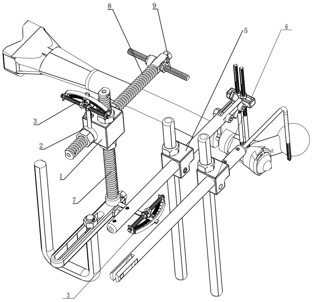
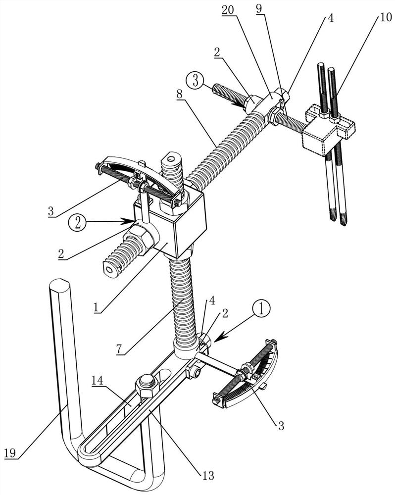
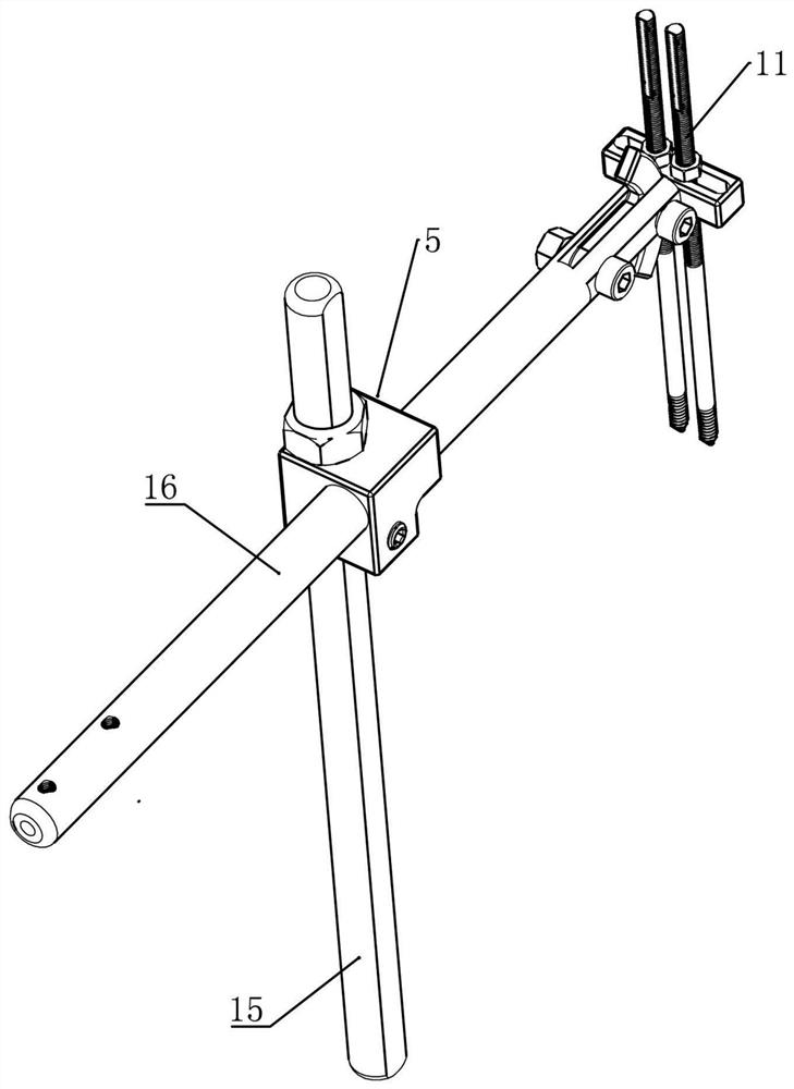
[0047] Example 1: A fracture traction reduction device, the device adopts an adjustable traction component such as figure 2 shown, using mating traction assemblies such as image 3 shown.

[0048] figure 2 The adjustment and traction assembly in the device mainly includes a threaded column 7, a threaded transverse rod 8 and a threaded longitudinal rod 9, a first node, a second node and a third node.

[0049] The upright column 7 is connected with the outer support through a first node, the upright column is perpendicular to the cross bar and connected by a second node, and the end of the cross bar is perpendicular to the longitudinal bar and connected by a third node.

[0050] The structure of the outer bracket is not limited, and any existing outer bracket for fixing the rod can be used. figure 2 As shown, a bar-shaped hole 14 is provided on the outer adjusting frame 13, and one end of a U-shaped outer fixing frame 19 is inserted and fixed in the proper position of the ...

Embodiment 2

[0065] Embodiment 2: On the basis of Embodiment 1, the vertical movement adjustment mechanism in this embodiment is provided with a vertical through hole vertically through the end point of the node 1 (outer adjustment frame 13 ), and the vertical hole is matched with a sleeve. There is a rotating sleeve 21 with an angle adjustment mechanism. The rotating sleeve 21 is matched with a threaded column 7. An anti-rotation key or track or special-shaped section is arranged between the rotating sleeve 21 and the threaded column 7. For the lock nut 18 on the column, loosen one lock nut and screw the other lock nut to drive the node 1 to reciprocate vertically relative to the column.

[0066] The lateral movement adjustment mechanism in this embodiment is provided with a transverse perforation on the main body of the node 2 or node 3 along the lateral direction. 8. An anti-rotation key or track or special-shaped section is set between the rotating sleeve 21 and the threaded cross bar ...

Embodiment 3

[0068] Embodiment 3: On the basis of Embodiment 1, the above various adjustment mechanisms are respectively replaced with the following Figure 10 Angle adjustment mechanism shown. Figure 10 It can be seen that a radial connecting plate 201 is extended and fixed on the outer side of the rotating sleeve 21, and an arc-shaped hole 202 is provided on the radial connecting plate 201. The locking wire 203, after loosening the locking wire 203, can ensure that the rotating sleeve 21 only rotates in the through hole of the node, and can lock the rotating sleeve 21 after tightening the locking wire 203.


PUM


Abstract

The invention discloses a fracture traction reduction device which comprises two sets of traction assemblies, each traction assembly comprises a threaded stand column, a threaded transverse rod and a threaded longitudinal rod, the threaded stand column is connected with an outer support through a first node, the stand column is perpendicular to the transverse rod and connected with the transverse rod through a second node, and the tail end of the transverse rod is perpendicular to the longitudinal rod and connected with the longitudinal rod through a third node. The first node and / or the second node are / is provided with a vertical movement adjusting mechanism and a vertical angle adjusting mechanism, the second node / or the third node is provided with a transverse movement adjusting mechanism and a transverse angle adjusting mechanism, and the third node is provided with a longitudinal movement adjusting mechanism and a longitudinal angle adjusting mechanism. Movement and angle adjustment are conducted through the two traction reduction mechanisms, so that the positions of bone seams at the far end and the near end of a fracture correspond, then pushing reduction butt joint and fixing are achieved, the stability degree is high after bone seam butt joint is supported by all steel pieces, and follow-up surgical operation is facilitated.

Description

technical field [0001] The invention belongs to the technical field of fracture positioning and fixing instruments, and in particular relates to a fracture site reduction device capable of accurately performing multi-step compound adjustment and fixation. Background technique [0002] Femoral shaft fractures and distal femoral fractures are common clinical fractures. Surgical treatment is the preferred treatment method. Before intramedullary nailing and bone plate fixation, both ends of the fracture site need to be reduced, docked and fixed. Traction is an important means to reduce femoral fractures and restore the length of lower limbs. At present, the retractors used in the reduction of patients with lower extremity fractures in various hospitals mainly include a traction rope and a pulley. One end of the traction rope is connected to the bracket at the fracture site, and the other end bypasses the pulley and then hangs the weights, and manually increase the number of wei...

Claims


Application Information

Patent Timeline
Patent Type & Authority Applications(China)
IPC IPC(8): A61B17/66
CPCA61B17/66A61B17/6408
Inventor 陈聚伍
Owner 陈聚伍
Why Eureka
Try Eureka