Bipolar parallel multi-terminal direct current power transmission system electric current modulus longitudinal differential protection method

A DC transmission system, multi-terminal DC technology, applied in the direction of emergency protection circuit devices, automatic disconnection emergency protection devices, electrical components, etc., can solve the problem of inability to distinguish between single-pole faults and inter-pole faults, pole selection, and is not applicable to multi-terminal systems , fast action and low reliability, and achieve the effects of strong selectivity, strong adaptability, and strong resistance to transition resistance

Active Publication Date: 2017-06-13
菏泽福之源电气设备有限公司
View PDF4 Cites 22 Cited by
  • Summary
  • Abstract
  • Description
  • Claims
  • Application Information

AI Technical Summary

Problems solved by technology

Traditional differential protection is affected by distributed capacitive current, and its quick action and reliability are not high
Chinese patents CN200910022923.6 and CN201110349980.2 respectively propose DC line differential protection methods based on distribut

Method used


Image

  • Bipolar parallel multi-terminal direct current power transmission system electric current modulus longitudinal differential protection method
  • Bipolar parallel multi-terminal direct current power transmission system electric current modulus longitudinal differential protection method
  • Bipolar parallel multi-terminal direct current power transmission system electric current modulus longitudinal differential protection method

Examples


Embodiment Construction

[0047] The present invention will be described in further detail below in conjunction with the accompanying drawings.

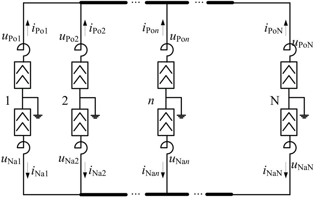
[0048] see figure 1 As shown in the figure, the parallel bipolar N-terminal DC transmission system, the DC line is located between the converter stations, and the branches of each converter station are connected in parallel to the high-voltage DC trunk line. The DC shunt is located outside the smoothing reactor on the DC side of the converter station. u Po1 , u Na1 i Po1 i Na1 ; u Po2 , u Na2 i Po2 i Na2 ; u Pon , u Nan i Pon i Nan ; u PoN , u NaN i PoN i NaN are the positive and negative DC voltages and currents sampled by the protection devices of the first terminal, the second terminal, the nth terminal and the Nth terminal, respectively. The sampling frequency is not less than 1Hz.

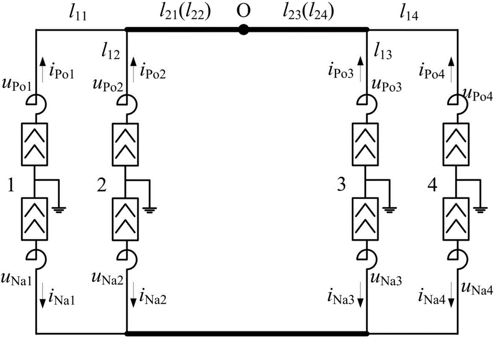
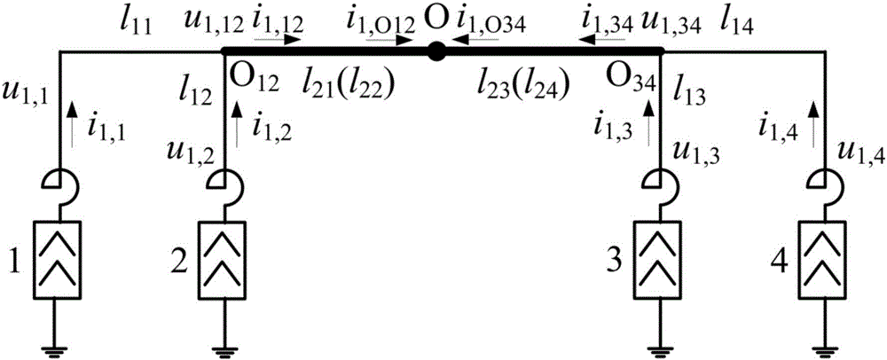
[0049] see figure 2 As shown, taking the bipolar four-terminal direct current transmission system as an example, the method of the present invention is in...


PUM


Abstract

The invention discloses a bipolar parallel multi-terminal direct current power transmission system electric current modulus longitudinal differential protection method. The method comprises the steps that digital sampling and modulus decoupling are conducted in each converter station of the parallel system, and 1, 0-mode voltage and electric current are obtained; one point on the direct current main line is selected as the destination point of calculation, starting from each converter station, the line terminal voltage, the electric current up to the destination point are calculated segment-by-segment and the 1, 0-mode differential current is obtained through the overlay at the destination point. If the 1-mode differential current is greater than the fault threshold, the fault is an internal area fault, otherwise the fault is an external fault; if the 0-mode differential current is greater than the threshold, the fault is a positive pole grounding fault; if the 0-mode differential current is less than the threshold, the fault is a negative pole grounding fault; if the 0-mode differential current is between the positive and negative selection thresholds, the fault is an inter polar short-circuit fault. The differential protection method is fast in movement speed, high in transition resistance capability, and is not under the influence of capacitive current in distribution, and can be extended to arbitrary end parallel direct current systems, in principle can recognize the fault type and is strong in adaptability. According to the differential protection method, the required sampling rate is low, the method is easy to implement and has practical value.

Description

technical field [0001] The invention relates to the field of relay protection for direct current transmission in electric power systems, in particular to current longitudinal protection for super / ultra-high voltage direct current transmission lines. Background technique [0002] The development of double-terminal direct current transmission system in my country is becoming more and more mature, but there are problems such as single location of the sending and receiving end system of the interconnection system, and tight line channels. The multi-terminal DC transmission system has the characteristics of large transmission power, low line cost and flexible control mode of the traditional DC transmission system, and overcomes the problems existing in the double-terminal system. It is the development trend of the future DC transmission technology. The double-terminal DC transmission systems that have been built include the Italy-Corsica-Sardinia three-terminal DC system and the ...

Claims


Application Information

Patent Timeline
IPC IPC(8): H02H7/26H02H3/26
CPCH02H3/265H02H7/268
Inventor 高淑萍刘琪宋国兵
Owner 菏泽福之源电气设备有限公司
Why Eureka
Try Eureka