Crankshaft crank throw upsetting, forming and axial positioning combined die

An axial positioning and combined technology, which is applied in the field of molds for crankshaft crankshaft upsetting and forging, can solve the problems of inconvenient repair and use, high material cost and high production cost, and achieve simple and convenient processing, reduce mold production costs, and simplify processing and manufacturing Effect

Active Publication Date: 2017-06-16
LIAONING 518 INTERNAL COMBUSTION ENGINE FITTINGS
View PDF7 Cites 7 Cited by
  • Summary
  • Abstract
  • Description
  • Claims
  • Application Information

AI Technical Summary

Problems solved by technology

[0014] However, the material cost and production cost of the whole upper right mold f4, lower right mold f6, uppe...

Method used


Image

  • Crankshaft crank throw upsetting, forming and axial positioning combined die
  • Crankshaft crank throw upsetting, forming and axial positioning combined die
  • Crankshaft crank throw upsetting, forming and axial positioning combined die

Examples


Embodiment Construction

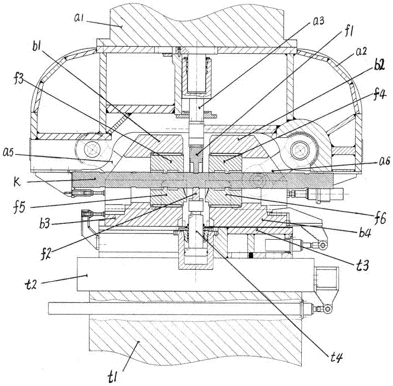
[0069] Referring to the embodiments shown in the accompanying drawings, the crankshaft forming of the present invention is described sequentially from the right end to the left end of the crankshaft bar K as a representative.

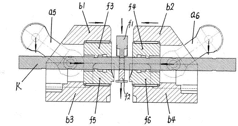
[0070] The crankshaft crankshaft upset forging forming axial positioning combined mold of the present invention comprises: the left upper die f3 installed on the left upper die base b1, the left lower die f5 installed on the left lower die base b3, and the right upper die installed on the right upper die base b2 f4, the right lower die f6 installed on the right lower die base b4.

[0071] Its characteristics are:

[0072] The right upper die f4 installed on the right upper die base b2 is composed of 4 axially stacked modules; the right lower die f6 installed on the right lower die base b4 is composed of 4 axially stacked modules; The 4 mold pieces on the right upper mold f4 on the right upper mold base b2 are combined with the 4 mold pieces installed o...


PUM


Abstract

The invention discloses a crankshaft crank throw upsetting, forming and axial positioning combined die. Each of a right upper die (f4), a right lower die (f6), a left upper die (f3) and a left lower die (f5) installed on a right upper die base (b2), a right lower die base (b4), a left upper die base (b1) and a left lower die base (b3) consists of four die pieces superposed axially, the four die pieces of the upper die and the four die pieces of the lower die are vertically and correspondingly combined in a one-to-one mode, the die pieces can be machined by using one round plate material to form an inner cavity and then are divided into the corresponding upper and lower die pieces through linear cutting, machining is simple and convenient, and the die pieces can be mutually replaced and used. Compared with manufacturing of an integral die, the die machining material cost and the die manufacturing cost can be greatly reduced, and the shortcoming that the whole die is required to be manufactured after local parts of the integral die are damaged is overcome.

Description

technical field [0001] The invention relates to a mold for crankshaft crankshaft upsetting and forging, that is, the crankshaft bar [0002] An extrusion die for axially positioning the crankshaft bar stock when the crankshaft is formed by the TR method. Background technique [0003] The crankshaft crankshaft upsetting and forging forming method of the TR method is to use a special upsetting forging tool to form the crankshaft bar blank on a hydraulic press, and locally heat the blank to form a crankshaft for each upsetting, then replace the mold, and then upset the blank Forging the next crank throw, and so on, until all the crank throws are formed by upset forging on the crankshaft bar blank. [0004] In actual production, a batch of crankshaft bar blanks are first forged to form the same crank throw, and then the mold is replaced, and then the batch of blanks are separately upset and forged to form the next crank throw, and so on, until the batch of crankshaft rods All ...

Claims


Application Information

Patent Timeline
IPC IPC(8): B21J13/02B21K1/08
CPCB21J13/02B21K1/08
Inventor 邓军疆焉永才吴丽萍韩晓光陈莉侯东波邓文婷李春阳
Owner LIAONING 518 INTERNAL COMBUSTION ENGINE FITTINGS
Why Eureka
Try Eureka