Simultaneous movement mechanism and equipment provided with simultaneous movement mechanism

A technology of synchronous movement and rotating shaft, applied in the direction of pivot connection, etc., can solve the problems of stuck, different friction of the intermediate guide body, etc., to achieve the effect of smooth transmission, better processing cost, and no risk of stuck

Inactive Publication Date: 2017-06-16
江苏东方滤袋股份有限公司
View PDF1 Cites 0 Cited by
  • Summary
  • Abstract
  • Description
  • Claims
  • Application Information

AI Technical Summary

Problems solved by technology

As a result, during the rotation process, the friction force of the intermediate guide body on the two rotating shafts is different
It is easy to cause the phenomenon of Caton

Method used


Image

  • Simultaneous movement mechanism and equipment provided with simultaneous movement mechanism
  • Simultaneous movement mechanism and equipment provided with simultaneous movement mechanism
  • Simultaneous movement mechanism and equipment provided with simultaneous movement mechanism

Examples


Embodiment 1

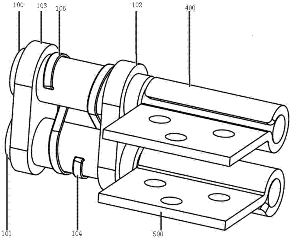
[0026] Such as Figure 1-5 As shown, the synchronous movement mechanism of this embodiment includes a first rotating shaft 100 , a second rotating shaft 101 , a first guide 102 , a second guide 103 , a first elastic member 104 , and a second elastic member 105 .

[0027] The first rotating shaft 100 is sequentially sleeved with the first guide member 102, the first elastic member 104, the second elastic member 105, and the second guide member 103, and the second rotating shaft 101 is sequentially sleeved with the first guide member 102, the first elastic member 104, The second elastic member 105 , the second guide member 103 , the first elastic member 104 and the second elastic member 105 are oppositely fixed on the first rotating shaft 100 and the second rotating shaft 101 respectively.

[0028] The first elastic member 104 and the second elastic member 105 have the same structure and are S-shaped elastic steel belts. In other embodiments, elastic fibers or chains with a larg...

Embodiment 2

[0036] In this embodiment, the fixed points of the first elastic member and the second elastic member on the second rotating shaft coincide, so the elastic component 114 in this embodiment is Figure 6 and Figure 7 In the structure shown, the ends of the two S-shaped elastic members are integrally fixed on the second rotating shaft, and the other two head ends are respectively fixed on the first rotating shaft.

[0037] Other implementations are the same as in Example 1.


PUM


Abstract

The invention discloses a synchronous movement mechanism and equipment using the mechanism, comprising at least one set of elastic components, the elastic components including at least two elastic parts, the first end of the first elastic part is fixed on the first rotating shaft, The end is fixed on the second rotating shaft after passing through the axis line connecting the first rotating shaft and the second rotating shaft, the head end of the second elastic member is fixed on the second rotating shaft, and the end passes through the connecting line connecting the axes of the first rotating shaft and the second rotating shaft Finally, it is fixed on the first rotating shaft; the projections of the first elastic member and the second elastic member on the cross-section of the first rotating shaft and the second rotating shaft have an intersection point; the first rotating shaft and the second rotating shaft are respectively sleeved on the on the guide. Using the synchronous transmission mechanism of the present invention, the synchronous rotation of the two rotating shafts can be smoothly realized, the processing cost is better, and there is no risk of jamming at the same time, the transmission is stable, and the elastic members are fixed on the rotating shaft in opposite directions so that the two rotating shafts can move in opposite directions. turn.

Description

technical field [0001] The invention relates to a connection device applied to electronic equipment, and in particular provides a synchronous motion mechanism and equipment using the mechanism. Background technique [0002] Existing devices generally include two bodies and connecting means connecting the two bodies. The two main bodies may be the cover and the main body of the notebook, or two main bodies that need to be rotationally connected on mechanical equipment or numerical control equipment. In order to realize that the two connecting devices can rotate synchronously, the connecting device is usually provided with two rotating shafts. Chinese invention patent application CN 104930049A, a connection device and equipment, on the guide body are provided with a first storage groove for accommodating the first synchronizing part, a second accommodating groove for accommodating the second synchronizing part and a The guide groove for accommodating the limiting part is bet...

Claims


Application Information

Patent Timeline
Patent Type & Authority Applications(China)
IPC IPC(8): F16C11/04F16C11/12
Inventor 戴学树
Owner 江苏东方滤袋股份有限公司
Why Eureka
Try Eureka