Multifunctional spring tester

A testing machine, multi-functional technology, applied in elastic testing, testing of mechanical components, testing of machine/structural components, etc., can solve the problems of spring breakage, injury, lack of spring force detection and fatigue detection, etc., to achieve easy observation , not easy to break, easy to operate

Active Publication Date: 2017-06-16
彭州市长庆全成技术开发有限公司
View PDF7 Cites 5 Cited by
  • Summary
  • Abstract
  • Description
  • Claims
  • Application Information

AI Technical Summary

Problems solved by technology

[0003] The purpose of the present invention is to provide a multifunctional spring testing machine, which solves the lack of detection equipment integrating spring force detection

Method used


Image

  • Multifunctional spring tester
  • Multifunctional spring tester
  • Multifunctional spring tester

Examples


Embodiment 1

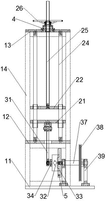
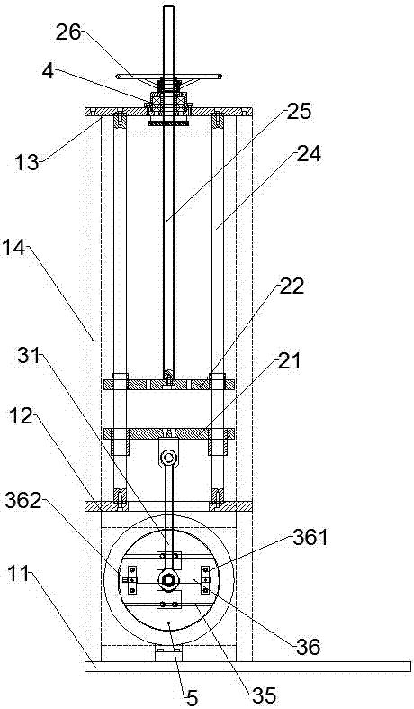
[0025] A multi-functional spring testing machine, comprising a fixed frame, an eccentric mechanism and a pressure testing mechanism, the fixed frame includes a horizontally arranged base 11, a first support plate 12, a second support plate 13 and a vertically arranged support column 14, the support column 14 has more than four and the lower end of the support column 14 is fixed on the base 11, the second support plate 13 is fixed on the upper end of the support column 14, the first support plate 12 is located between the second support plate 13 and the base 11 and passes through The support column 14 is fixed, the eccentric mechanism is located between the first support plate 12 and the base 11 and is fixed on the base 11, the pressure test mechanism is fixed above the first support plate 12, and organic glass is fixed between the adjacent support columns 14 plate.

[0026] In this embodiment, not only the spring fatigue test, but also the spring force test of the spring can b...

Embodiment 2

[0028]On the basis of Embodiment 1, the optimization and improvement are carried out. The pressure testing mechanism includes a lower moving plate 21, an upper moving plate 22, a guide shaft 24, a lead screw 25 and a hand wheel 26. There are more than four guide shafts 24 and they are arranged vertically. The edges of the moving plate 21 and the upper moving plate 22 are uniformly provided with more than four through holes, and the lower end of the guide shaft 24 passes through the upper moving plate 22 and the lower moving plate 21 in turn and is fixed on the first support plate 12. The lower end of 25 is fixed on the center of upper moving plate 22 , the upper end of leading screw 25 passes through second support plate 13 , and hand wheel 26 is enclosed within on the leading screw 25 and is arranged on the top of second support plate 13 .

[0029] In this embodiment, during the testing process, the spring is placed between the lower moving plate and the upper moving plate. Un...

Embodiment 3

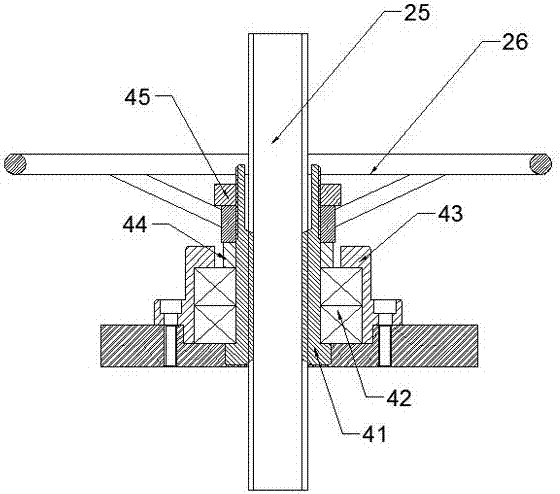
[0031] On the basis of Embodiment 2, optimization and improvement are carried out. A locking block 4 is provided at the joint between the second support plate 13 and the lead screw 25. The locking block 4 includes a lead screw nut 41, a lead screw bearing 42 and an upper cover 43. The rod nut 41 is sleeved on the leading screw 25, the leading screw bearing 42 is sleeved on the outside of the leading screw nut 41, the upper cover 43 is a hollow structure and the diameter of the upper opening of the upper cover 43 is smaller than the lower opening diameter of the upper cover 43, and the upper cover The upper opening diameter of 43 is larger than the diameter of the screw nut 41 , and the upper cover 43 is mounted on the outside of the screw bearing 42 and fixed on the second support plate 13 .

[0032] The outer side of screw nut 41 is also covered with washer 44, washer 44 is arranged on the top of lead screw bearing 42 and is positioned at the upper opening of loam cake 43, and...


PUM


Abstract

The invention discloses a multifunctional spring tester, which comprises a fixing frame, an eccentric mechanism and a pressure test mechanism, wherein the fixing frame comprises a horizontally-arranged base, a first supporting plate, a second supporting plate and more than four vertically-arranged supporting columns; the lower ends of the supporting columns are fixed on the base; the second supporting plate is fixed at the upper end of the supporting column; the first supporting plate is located between the second supporting plate and the base and is fixed through the supporting columns; the eccentric mechanism is located between the first supporting plate and the base and is fixed on the base; the pressure test mechanism is fixed above the first supporting plate; and a perspex sheet is fixed between adjacent supporting columns. Spring fatigue test can be carried out, spring force test can also be carried out, the operation is simple, and due to the perspex sheet, the spring test condition can be observed, and the spring can be prevented from being broken and hurting a person in the case of spring fatigue test.

Description

technical field [0001] The invention relates to spring testing equipment, in particular to a multifunctional spring testing machine. Background technique [0002] At present, the detection settings for springs in China can only be to detect the spring force of the spring through the spring force detection equipment, or to detect the fatigue life of the spring through the spring fatigue detection equipment, so there is a lack of detection equipment integrating spring force and fatigue detection. Long operations are complex. Contents of the invention [0003] The purpose of the present invention is to provide a multifunctional spring testing machine, which solves the lack of detection equipment integrating spring force detection and fatigue detection at present, and can not only facilitate observation during spring testing, but also avoid spring fracture damage during spring fatigue testing. human problem. [0004] In order to solve the above-mentioned technical problems, ...

Claims


Application Information

Patent Timeline
IPC IPC(8): G01M5/00G01M13/00
CPCG01M5/005G01M13/00
Inventor 刘超赵游凯陈林
Owner 彭州市长庆全成技术开发有限公司
Why Eureka
Try Eureka