Multifunctional spring testing machine
A testing machine, multi-functional technology, applied in elastic testing, testing of mechanical components, testing of machine/structural components, etc., can solve the problems of spring breakage, injury, lack of spring force detection and fatigue detection, etc., so as to facilitate observation , not easy to break, easy to operate
- Summary
- Abstract
- Description
- Claims
- Application Information
AI Technical Summary
Problems solved by technology
Method used
Image
Examples
Embodiment 1
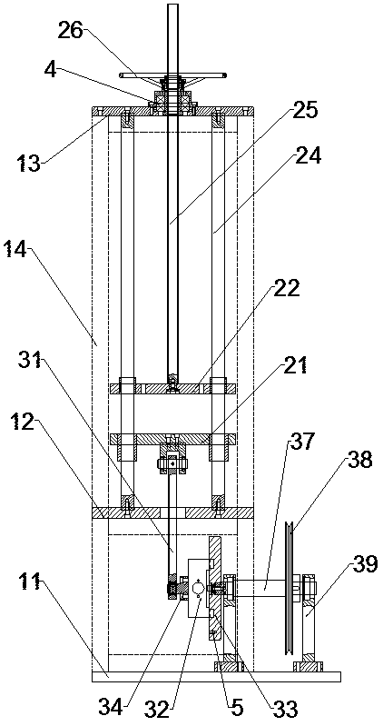
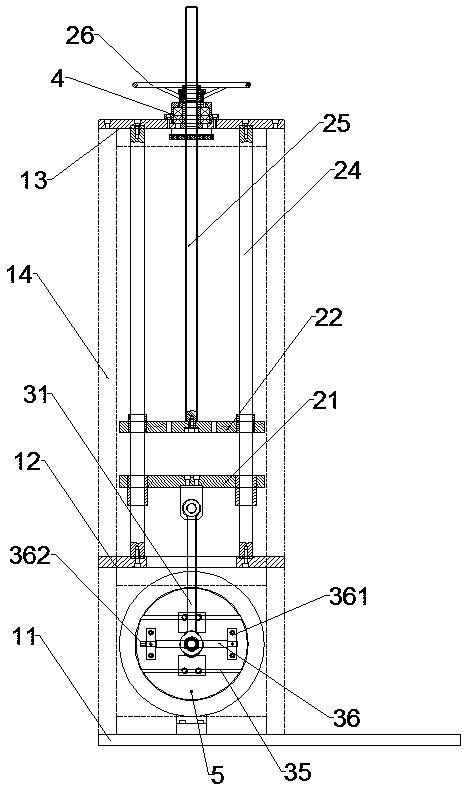
[0025] A multi-functional spring testing machine, comprising a fixed frame, an eccentric mechanism and a pressure testing mechanism, the fixed frame includes a horizontally arranged base 11, a first support plate 12, a second support plate 13 and a vertically arranged support column 14, the support column 14 has more than four and the lower end of the support column 14 is fixed on the base 11, the second support plate 13 is fixed on the upper end of the support column 14, the first support plate 12 is located between the second support plate 13 and the base 11 and passes through The support column 14 is fixed, the eccentric mechanism is located between the first support plate 12 and the base 11 and fixed on the base 11, the pressure test mechanism is fixed above the first support plate 12, and organic glass is fixed between the adjacent support columns 14 plate.
[0026] In this embodiment, not only the spring fatigue test, but also the spring force test of the spring can be p...
Embodiment 2
[0028]On the basis of Embodiment 1, the optimization and improvement are carried out. The pressure testing mechanism includes a lower moving plate 21, an upper moving plate 22, a guide shaft 24, a lead screw 25 and a hand wheel 26. There are more than four guide shafts 24 and they are arranged vertically. The edges of the moving plate 21 and the upper moving plate 22 are uniformly provided with more than four through holes, and the lower end of the guide shaft 24 passes through the upper moving plate 22 and the lower moving plate 21 in turn and is fixed on the first support plate 12. The lower end of 25 is fixed on the center of upper moving plate 22 , the upper end of leading screw 25 passes through second support plate 13 , and hand wheel 26 is enclosed within on the leading screw 25 and is arranged on the top of second support plate 13 .
[0029] In this embodiment, during the testing process, the spring is placed between the lower moving plate and the upper moving plate. Un...
Embodiment 3
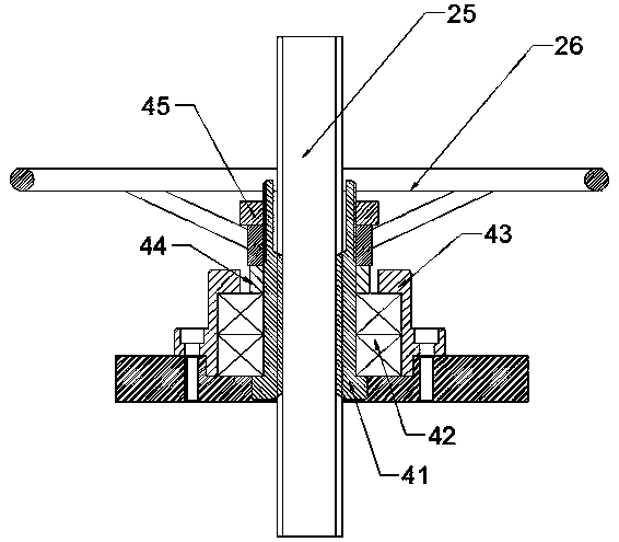
[0031] On the basis of Embodiment 2, optimization and improvement are carried out. A locking block 4 is provided at the joint between the second support plate 13 and the lead screw 25. The locking block 4 includes a lead screw nut 41, a lead screw bearing 42 and an upper cover 43. The rod nut 41 is sleeved on the leading screw 25, the leading screw bearing 42 is sleeved on the outside of the leading screw nut 41, the upper cover 43 is a hollow structure and the diameter of the upper opening of the upper cover 43 is smaller than the lower opening diameter of the upper cover 43, and the upper cover The upper opening diameter of 43 is larger than the diameter of the screw nut 41 , and the upper cover 43 is mounted on the outside of the screw bearing 42 and fixed on the second support plate 13 .
[0032] The outer side of screw nut 41 is also covered with washer 44, washer 44 is arranged on the top of lead screw bearing 42 and is positioned at the upper opening of loam cake 43, and...
PUM
 Abstract
Description
Claims
Application Information
 - R&D
- Intellectual Property
- Life Sciences
- Materials
- Tech Scout
- Unparalleled Data Quality
- Higher Quality Content
- 60% Fewer Hallucinations
Browse by: Latest US Patents, China's latest patents, Technical Efficacy Thesaurus, Application Domain, Technology Topic, Popular Technical Reports.
© 2025 PatSnap. All rights reserved.Legal|Privacy policy|Modern Slavery Act Transparency Statement|Sitemap|About US| Contact US: help@patsnap.com


