Method for producing clearance at drive shaft, drive shaft and axial piston machine

A technology of axial piston machines and drive shafts, applied in shafts and bearings, reciprocating piston engines, manufacturing tools, etc., can solve cost-intensive and time-intensive problems, reduce manufacturing costs, improve process reliability, The effect of shortening the process chain

Active Publication Date: 2021-03-12
ROBERT BOSCH GMBH
View PDF8 Cites 0 Cited by
  • Summary
  • Abstract
  • Description
  • Claims
  • Application Information

AI Technical Summary

Problems solved by technology

The disadvantage here is that the finishing step is cost-intensive and time-intensive

Method used


Image

  • Method for producing clearance at drive shaft, drive shaft and axial piston machine
  • Method for producing clearance at drive shaft, drive shaft and axial piston machine

Examples


Embodiment Construction

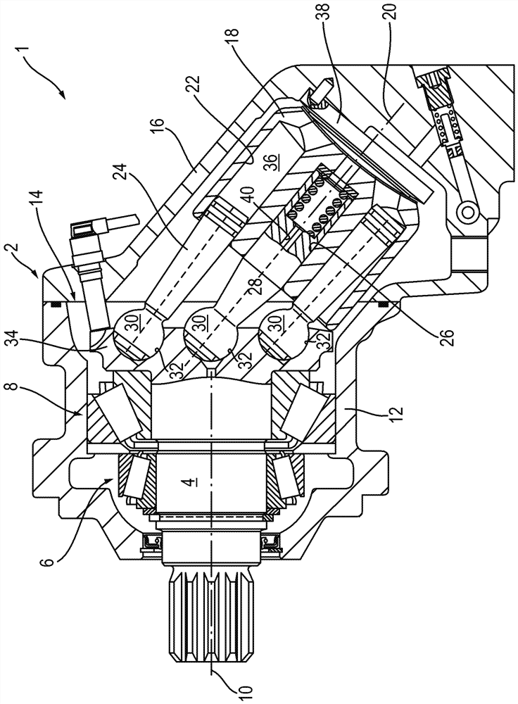
[0043] according to figure 1 An axial piston machine 1 constructed in an inclined-axis configuration has a two-part housing 2 in which a drive shaft 4 is rotatably mounted via two tapered roller bearings 6 and 8 , an axis of rotation 10 . Axial piston machine 1 according to figure 1 The exemplary embodiment of the present invention is designed as a constant machine, that is to say with a constant displacement, and can alternatively be configured with an adjustable displacement.

[0044] The drive shaft 4 is accommodated via bearings 6 , 8 in a pot-shaped first housing part 12 . At the mouth 14 of the housing, through which the drive shaft 4 can be mounted, abuts a second housing 16 inclined relative to the first housing 12 in which a rotation axis 20 The cylinder 18 is rotatably supported. In this case, the cylinder barrel 18 has a plurality of cylinder bores 22 on a pitch circle arranged concentrically to the axis of rotation 20 , in each case a working piston 24 is arranged...


PUM

PropertyMeasurementUnit
thicknessaaaaaaaaaa
thicknessaaaaaaaaaa
hardnessaaaaaaaaaa

Abstract

A method for manufacturing an at least sectionally spherical-cap-shaped recess on a drive shaft for a hydrostatic axial piston machine includes whirling of the recess and heat treatment of the recess to form a wear layer. A drive shaft for a hydrostatic axial piston machine includes at least one recess manufactured according to the method. A hydrostatic axial piston machine includes a drive shaft with at least one recess manufactured according to the method.

Description

technical field [0001] The invention relates to a method according to the invention for producing a ball-cap-shaped recess in a drive shaft, a drive shaft according to the invention with the recess and a hydrostatic shaft according to the invention with the drive shaft to the piston machine. Background technique [0002] The hydrostatic axial piston machine has a drive shaft with a drive flange, which is provided on the end side with a plurality of spherical cap-shaped recesses arranged on a pitch circle. The spherical heads of a guide piston and of working pistons of the cylinder of the axial piston machine are accommodated pivotably in these recesses. In this case, the working piston is embedded in the cylinder bore of the cylinder and is accommodated axially movable in order to transfer the torque during pressure changes and due to the tilting position of the drive shaft relative to the cylinder during motor operation. Transmission to the drive shaft and optionally conv...

Claims


Application Information

Patent Timeline
Patent Type & Authority Patents(China)
IPC IPC(8): B23P13/00C21D9/28B23C3/16
CPCB23C3/16B23P13/00C21D9/28C21D1/06F01B3/0032F01B3/0038F01B3/0085F04B1/128F16C3/02F01B3/0094
Inventor M.瓦格纳D.赫格
Owner ROBERT BOSCH GMBH
Why Eureka
Try Eureka