Car seat sliding rail locking mechanism

A car seat slide rail and locking mechanism technology, which is applied to vehicle seats, movable seats, vehicle parts, etc., can solve the problem that the locking synchronization cannot be reliably guaranteed, the length of the hook of the torsion spring cannot be too long, and the spring To solve the problems such as extremely high precision requirements of the chip, to achieve the effect of reliable locking, firm and reliable connection, and not easy to skip teeth

Active Publication Date: 2017-06-20
JIANGSU ZHONGMING XIANGHE SEIKO
View PDF7 Cites 6 Cited by
  • Summary
  • Abstract
  • Description
  • Claims
  • Application Information

AI Technical Summary

Problems solved by technology

However, the following problems have been exposed in the actual use process: first, because the locking mechanism is placed on the inner side of the upper guide rail installation surface, the distance between the locking pawl in the locking mechanism and the rotation center is relatively short, and the unlocking stroke of the slide rail is large, and the The required unlocking force is also large; secondly, the locking force of the locking mechanism is realized by the spring piece, which requires extremely high precision of the spring piece, and the locking synchronization cannot be reliably guaranteed.
However, there are problems in actual use: the locking mechanism is placed on the inner side of the mounting surface of the upper slide rail, and its unlocking stroke is also relatively large, and the required unlocking force is also large; in addition, the hook length of the torsion spring should not be too long , so the processing accuracy of the torsion spring is high, which not only increases the difficulty of torsion spring assembly, but also easily falls off

Method used


Image

  • Car seat sliding rail locking mechanism
  • Car seat sliding rail locking mechanism
  • Car seat sliding rail locking mechanism

Examples


Embodiment Construction

[0020] The applicant will describe in detail in the form of the following examples, but the description of the examples is not a limitation to the technical solution of the present invention, and any equivalent transformation made according to the concept of the present invention is only a formal rather than a substantive equivalent transformation All should be regarded as the scope of the technical solution of the present invention.

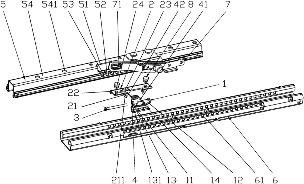
[0021] In the following descriptions, all concepts related to directionality or orientation of up, down, left, right, front and back are based on image 3 The position shown is a reference, so it cannot be understood as a special limitation on the technical solution provided by the present invention.

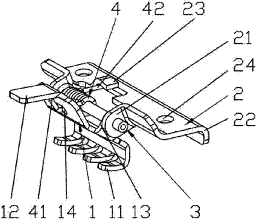
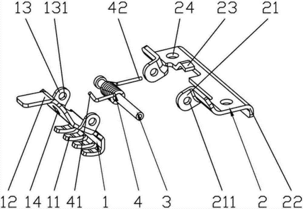
[0022] Please refer to figure 1 and combine figure 2 , image 3 , Figure 4 and Figure 5 , the present invention relates to a car seat slide rail locking mechanism, the car seat slide rail includes a moving guide rail 5, a fixed guide rail ...


PUM


Abstract

Provided is a car seat sliding rail locking mechanism. The locking mechanism comprises a movable guide rail, a fixed guide rail, a locking mechanism and an unlocking mechanism. The locking mechanism further comprises a locking claw, a fixed bracket, a rotating shaft and a locking spring. The lower end of the lock claw is provided with a plurality of lock gears; the upper end of the lock claw is provided with a control panel; the middle two sides of the lock claw is provided with a pair of first fold ears; a spring hole is installed at the connection part of the control panel and the lock gear; the one side of the fixed bracket is provided with a pair of second fold ears, and the other side of the fixed bracket is provided with a reinforced flanging and the middle of the fixed bracket is provided a hook spring slot; the locking spring is installed between a pair of the first fold ears, wherein a first spring hook at the one end is hooked up to the spring hole, and a second spring hook at the other end is hooked up to the hook spring groove; the middle of the rotating shaft is provided with the locking spring in a clamping mode, and both ends of the rotating shaft are passed through and formed in shaft holes of a pair of first fold ears and a pair of second fold ears; an abdication groove, a square hole and a lock groove are formed in the moving guide rail; a plurality of locking row holes are formed in the edgefold of the fixed guide rail; a wrench hole is formed in the locking mechanism. The sliding rail locking mechanism has the advantages that the locking strength is high; a gear of the locking mechanism is prevented from skipping under impact; the unlocking trip is short; the unlocking force is weak; the processing is convenient; the locking is reliable; the processing accuracy requirement is low and the assembling is convenient.

Description

technical field [0001] The invention belongs to the technical field of vehicle accessories, and in particular relates to a sliding rail locking mechanism of an automobile seat. Background technique [0002] The car seat slide rail usually includes a moving guide rail, a fixed guide rail, a locking mechanism and an unlocking mechanism. Its function is to change the front and rear positions of the seat and lock the seat. above is required. In this regard, a detailed understanding can be obtained in previously published Chinese patent documents, such as the Chinese Invention Patent Authorization No. CN104108322B and the Chinese Utility Model Patent No. CN204055428U, which are described in detail. [0003] The former discloses a "car seat slide rail", which adopts a built-in single-side locking mechanism, and its achievements are: compact structure, high static locking strength, and small clearance. However, the following problems have been exposed in the actual use process: f...

Claims


Application Information

Patent Timeline
Patent Type & Authority Applications(China)
IPC IPC(8): B60N2/08B60N2/07
CPCB60N2/0722B60N2/08Y02T10/40
Inventor 邹耀忠
Owner JIANGSU ZHONGMING XIANGHE SEIKO
Why Eureka
Try Eureka