Multi-rotor wing unmanned aerial vehicle arm fast folding device
A multi-rotor unmanned and folding device technology, applied in the field of drones, can solve the problems of inability to realize fast folding and unfolding, complex structure of the arm folding parts, cumbersome operation, etc., to achieve convenient operation, ensure structural strength, folding and The effect of simple unfolding process
- Summary
- Abstract
- Description
- Claims
- Application Information
AI Technical Summary
Problems solved by technology
Method used
Image
Examples
Embodiment 1
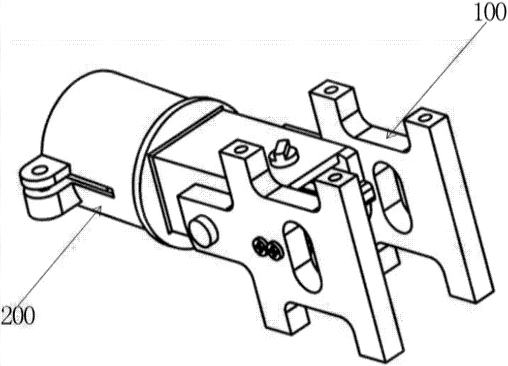
[0027] Such as figure 1 As shown, this embodiment provides a device for quickly folding the arms of a multi-rotor UAV, including a fixing unit 100 and a folding unit 200 . Wherein, the fixing unit 100 is fixed on the frame of the drone, the folding unit 200 is fixed to the arm of the drone, and the folding unit 200 can be unfolded or folded relative to the fixing unit 100 .
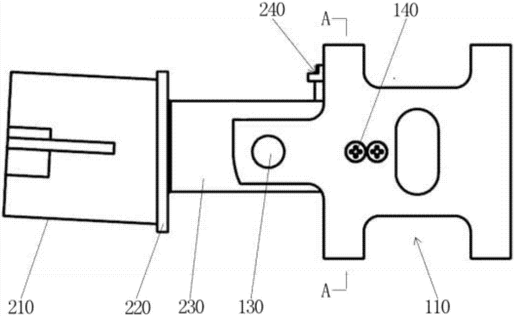
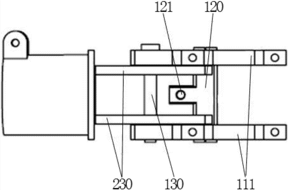
[0028] Such as Figure 2-4 As shown, the fixing unit 100 includes a fixing frame 110 , a guide plate 120 , a connecting shaft 130 and several bolts 140 .
[0029] The fixing frame 110 includes two fixing plates 111 arranged in parallel. The fixed plate 111 is fixed on the frame for supporting other components. The shape and size of the fixing plate 111 are set according to the frame. The fixing plate 111 has a square hole 112 .
[0030] The guide plate 120 is in a “convex” shape, and both sides match the square holes 112 of the fixing plate 111 . The guide plate 120 is arranged in the fixed frame 11...
Embodiment 2
[0045] Such as Figure 10 As shown, this embodiment provides a quick-folding device for the arms of a multi-rotor UAV, which is basically the same in structure as the first embodiment, the only difference being that the limit assembly 240 also includes a return elastic member 244 . In this embodiment, the reset elastic member 244 is a spring. The spring 244 is disposed between the pin hole 2411 and the snap ring 243 .
[0046] When the limiting pin 242 is pulled out from the limiting hole 121 , the spring 244 is compressed. When the limiting pin 242 needs to be inserted, the limiting pin 242 is aligned with the limiting hole 121 , and the compressed spring 244 pushes the limiting pin 242 into the limiting hole 121 . The spring 244 can also prevent the limiting pin 242 from falling out of the limiting hole 121 when the drone performs operations such as turning over.
PUM
 Abstract
Description
Claims
Application Information
 - R&D
- Intellectual Property
- Life Sciences
- Materials
- Tech Scout
- Unparalleled Data Quality
- Higher Quality Content
- 60% Fewer Hallucinations
Browse by: Latest US Patents, China's latest patents, Technical Efficacy Thesaurus, Application Domain, Technology Topic, Popular Technical Reports.
© 2025 PatSnap. All rights reserved.Legal|Privacy policy|Modern Slavery Act Transparency Statement|Sitemap|About US| Contact US: help@patsnap.com


