Solar street lamp

A technology of solar street lamps and solar panels, applied in the field of solar street lamps, can solve the problems of complex overall structure, many structural equipment, and increased failure rate, and achieve the effects of firm fixing of light poles, simple overall structure, and stable and reliable operation

Inactive Publication Date: 2017-06-20
湖南大平安安全科技有限公司
View PDF4 Cites 1 Cited by
  • Summary
  • Abstract
  • Description
  • Claims
  • Application Information

AI Technical Summary

Problems solved by technology

[0002] With the development of solar technology, the application of solar energy on street lamps has become very mature. However, the high production cost of solar panels has led to the high cost of using solar street lamps. Therefore, without affecting the normal use of solar street lamps, as much as possible The reduction of production cost will be the main problem to be overcome at present
At present, there is a requirement in the market to change the solar circuit to save the electricity consumption of LED lights, thereby reducing electricity consumption, but this is to achieve the requirement of saving electricity by sacrificing the brightness of LED lights, and adding devices such as light chasers, so that Solar energy can absorb more electric energy, but a lot of equipment needs to be added. Although the electric energy is increased, the production cost remains high, the cost of use is high, there are too many structural equipment, the failure rate is greatly increased, and it is not easy to popularize
[0003] The solar street lamp in the above prior art has a relatively complicated overall structure, high production cost, and the installation of the solar street lamp is not firm.
At the same time, solar street lamps in the prior art usually use a photosensitive switch to control the on-off of the circuit, so that it can store energy during the day and turn on the light at night, and it will also turn on when no one passes by, thus causing a waste of energy.

Method used


Image

  • Solar street lamp
  • Solar street lamp

Examples


Embodiment Construction

[0016] An embodiment of the present invention will be described in detail below in conjunction with the accompanying drawings.

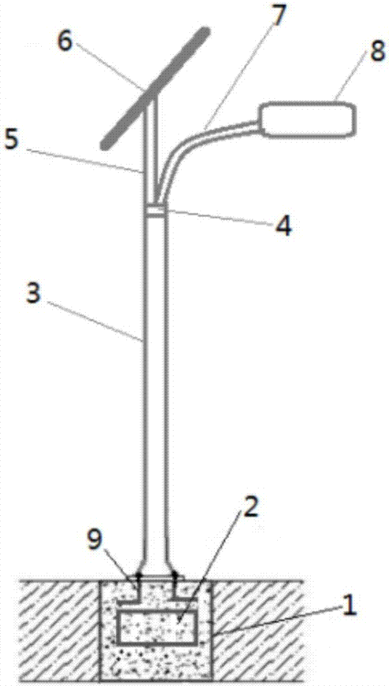
[0017] Such as figure 1 As shown, a solar street lamp according to an embodiment of the present invention includes a base 1 , a battery 2 , a light pole 3 , a variable diameter joint 4 , a straight tube 5 , a solar panel 6 , a bent tube 7 , a street lamp 8 , and anchor screws 9 . The base 1 is pre-buried under the ground, the main body of the base is made of concrete, and the light pole 3 is fixed on the base 1 through the L-shaped anchor screw 9 pre-embedded on the main body of the base 1, so as to ensure The stability of the light pole, the base 1 is equipped with a battery 2, the upper end of the light pole 3 is connected to the reducing joint 4, the straight pipe 5 and the curved pipe 7 are connected to the variable diameter joint 4, and the other end of the curved pipe 7 is connected to the street lamp 8, so The upper end of the straight pipe 5...


PUM


Abstract

The invention relates to a solar street lamp which is mainly applied to road sections such as urban streets and rural highways needing night lighting. The solar street lamp comprises a lamp pole, a street lamp body, a solar battery and a storage battery; and the solar battery is installed at the top of the lamp pole, and the street lamp body is installed at the upper portion of the lamp pole; the solar street lamp further comprises a base embedded underground, the lamp pole is fixedly connected to the base, a main body of the base is made of concrete, four L-shaped anchor screws are embedded inside the base, and thread parts of the anchor screws are higher than the upper end face of the base. The main body of the base of the solar street lamp is made of the concrete, the lamp pole is fixedly connected to the base through the anchor screws embedded into the main body of the base, and therefore the lamp pole is fixed more firmly; according to the solar street lamp, the energy consumption and the installation line cost of the solar street lamp are reduced, the solar street lamp is environment-friendly, and the service life of the lamp is prolonged; and meanwhile, the overall structure is relatively simple, and the production cost is lower. In addition, a controller of the solar street lamp controls the solar street lamp to light when some pedestrian passes through the street lamp at night through a light-operated switch, a figure sensor and a power control module, and therefore energy waste is avoided.

Description

technical field [0001] The invention belongs to the technical field of lamps, in particular to a solar street lamp. Background technique [0002] With the development of solar technology, the application of solar energy on street lamps has become very mature. However, the high production cost of solar panels has led to the high cost of using solar street lamps. Therefore, without affecting the normal use of solar street lamps, as much as possible Reducing the production cost will be the main problem to be overcome at present. At present, there is a requirement in the market to change the solar circuit to save the electricity consumption of LED lights, thereby reducing electricity consumption, but this is to achieve the requirement of saving electricity by sacrificing the brightness of LED lights, and adding devices such as light chasers, so that Solar energy can absorb more electric energy, but a lot of equipment needs to be added. Although the electric energy is increased,...

Claims


Application Information

Patent Timeline
Patent Type & Authority Applications(China)
IPC IPC(8): F21S9/03F21V23/00F21V21/00F21V23/04H05B33/08F21W131/103F21Y115/10H05B44/00
CPCF21S8/086F21S9/035F21V21/00F21V23/003F21V23/02F21V23/0464F21V23/0471F21W2131/103H05B45/10Y02B20/72Y02B20/30
Inventor 陈昌龙刘晓芳
Owner 湖南大平安安全科技有限公司
Why Eureka
Try Eureka