A large-stroke multi-station stretching press

A multi-station, press technology, applied in the direction of presses, stamping machines, manufacturing tools, etc., can solve the problems of increased stress deformation of the crankshaft, complex transmission structure, and insufficiently stable transmission, etc., to achieve strong anti-eccentric load capability, transmission The effect of compact structure and smooth transmission

Active Publication Date: 2019-03-01
YANGLI GRP CORP LTD
View PDF1 Cites 0 Cited by
  • Summary
  • Abstract
  • Description
  • Claims
  • Application Information

AI Technical Summary

Problems solved by technology

When working, the crankshaft drives the upper toggle and the lower toggle to swing through the connecting rod, the lower toggle drives the slider to move up and down along the guide rail through the guide post, and the slider drives the upper mold to reciprocate up and down, and cooperates with the lower mold for stamping. The advantage is that the crankshaft is light in weight and low in manufacturing cost. However, due to the complex force of the crankshaft transmission, it is affected by torque and bending moment at the same time. When the eccentric stroke is large or the processing has subtle defects, there will be greater Risk of fracture, affected by its complex structure and force, the crankshaft can only be used in the transmission structure of the press with a small stroke; two connecting rods are arranged symmetrically on the crankshaft, and the connecting rods have a reaction force on the crankshaft, which increases the force on the crankshaft The risk of deformation, the connecting rod is hinged with the upper toggle and the lower toggle at the same time, the transmission structure is complex, the transmission is not stable enough, the span of the force point of the guide column at the lower end of the two symmetrical lower toggles is small, and the machine tool has poor anti-eccentric load capacity

Method used


Image

  • A large-stroke multi-station stretching press
  • A large-stroke multi-station stretching press
  • A large-stroke multi-station stretching press

Examples


Embodiment Construction

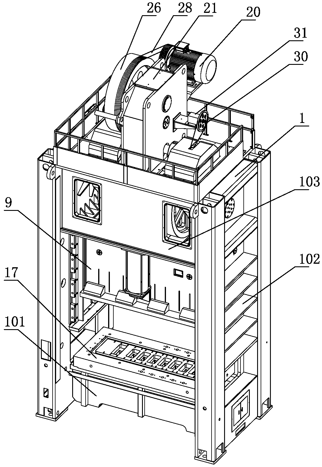
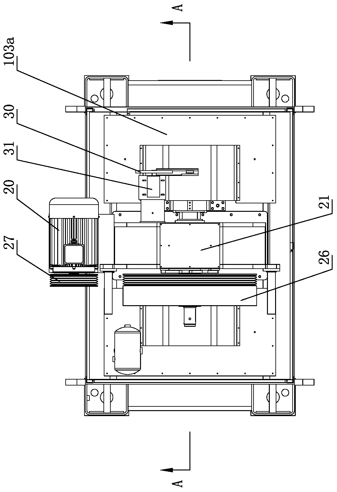
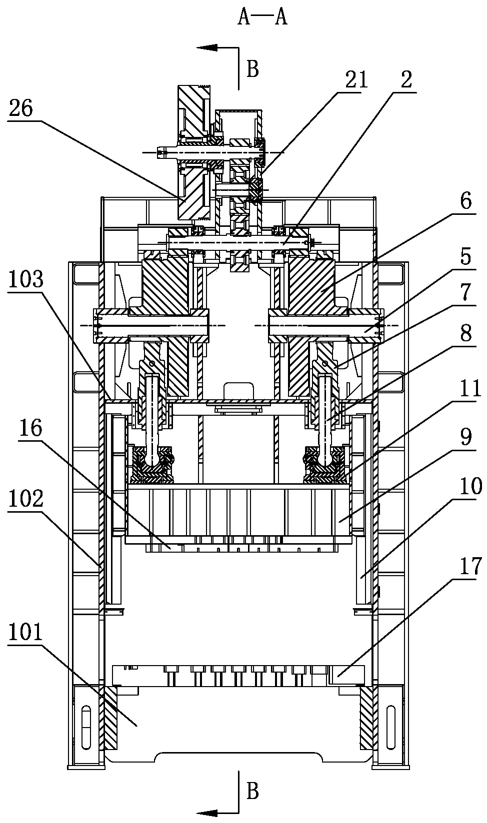
[0023] like Figure 1-9, is a large-stroke multi-station stretching press, comprising a machine body 1, a rotatable transmission shaft 2 is arranged horizontally on the upper part of the machine body 1, a first gear 3 is provided in the middle of the transmission shaft 2, two ends of the transmission shaft 2 Both ends are provided with second gears 4, and the first gears 3 are connected in transmission with the rotary drive mechanism. Power shafts 5 are respectively provided on the machine body corresponding to the second gears 4, and the axes of the two power shafts 5 coincide with each other. All are provided with eccentric gear 6, and eccentric gear 6 is meshed with corresponding second gear 4, and the eccentric wheel body of eccentric gear 6 is provided with connecting rod 7, and the bottom of connecting rod 7 is vertically provided with screw groove, and screw groove internal thread is connected with The ball screw 8 and the connecting rod 7 include a shaft 7a and a rod s...


PUM


Abstract

The invention discloses a large-stroke multi-station drawing press in the field of punching machines. The large-stroke multi-station drawing press comprises a press body, a transmission shaft is arranged on the upper portion of the press body, a first gear is arranged in the middle of the transmission shaft, second gears are arranged at the two ends of the transmission shaft, two power shafts are arranged on the press body, and eccentric gears are arranged on the power shafts and engaged with the corresponding second gears. The eccentric gears are provided with connecting rods, and the lower portions of the connecting rods are connected with bulb threaded rods through threads. A sliding block body is arranged below the press body, an external support is arranged on the upper portion of the sliding block body, an oil cylinder is arranged in the external support, bulb supports are arranged in the oil cylinder, and bulbs abut against spherical face grooves. Bulb cover plates are arranged between the external support and the bulb threaded rods, an external cover plate is arranged on the outer side of the external support, an upper die plate is arranged on the lower portion of the sliding block body, a lower die plate is arranged on the lower portion of the press body, a multi-station upper die is arranged on the upper die plate, and a multi-station lower die is arranged on the lower die plate. The large-stroke multi-station drawing press adopts the eccentric gears, the stroke of the press can be increased, the eccentric gears on the two sides are stable in transmission, the span of points of force application is large, and the unbalance loading resisting capacity is high.

Description

technical field [0001] The invention belongs to the field of stamping machine tools, in particular to a large-stroke multi-station stretching press. Background technique [0002] In the prior art, there is an overhead cylinder crankshaft toggle four-column press, its patent application number: 201310046472.6; application date: 2013.02.06; publication number: CN 103121294 A; publication date: 2013.05.29; its structure includes a base The frame of the press is fixed with the surrounding columns, the crankshaft is fixed on the upper beam, the crankshaft is connected with the upper toggle and the lower toggle through the connecting rod, and the connecting rod, upper toggle and lower toggle are connected with the square slide through the central axis The blocks are hinged together, the square slider can move laterally in the chute of the upper beam, the upper end of the upper toggle is connected with the anti-slider, the lower end of the lower toggle is connected with the upper e...

Claims


Application Information

Patent Timeline
Patent Type & Authority Patents(China)
IPC IPC(8): B21D24/00B30B1/26
CPCB21D24/00B30B1/266
Inventor 黄建民仲君王明柱钱琦
Owner YANGLI GRP CORP LTD
Why Eureka
Try Eureka