Steel frame of a switch cabinet
A technology of steel frame and switchgear, which is applied to the frame of substation/switchgear, details of substation/switch layout, electrical components, etc. Good stability, strong torsion resistance, and the effect of enhancing strength
- Summary
- Abstract
- Description
- Claims
- Application Information
AI Technical Summary
Problems solved by technology
Method used
Image

Examples
Embodiment 1
[0035] Example 1, with reference to the attached Figure 1-5 , 7-8.
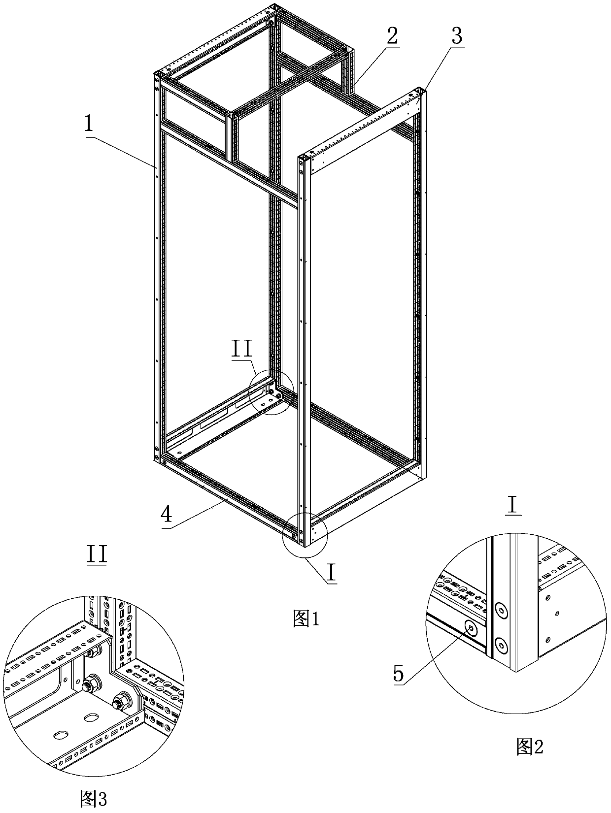
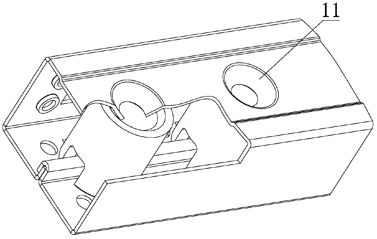
[0036] The steel frame of the switch cabinet of the present invention includes a column, a side beam 4, a small column 2 and a large beam 3. The column is fixedly connected to the side beam 4 and the large beam 3 respectively. Parallel to each other, the large beams 3 are parallel to each other, the side beams 4 and the large beams 3 are perpendicular to each other, and the small columns 3 are fixedly connected to the upper side beams 4; The steel frame also includes Corner fastening device, the structure of the corner fastening device as enlarged figure 2 The I site and magnification image 3 As shown in part II, the corner fastening device fixes the column 1, the side beam 4 and the large beam 3 together through fasteners 5 (such as fastening bolts), and the column adopts a rectangular closed profile 1. The sealing part of the profile 1 is provided with a confronting reinforcing rib device 12 .
[003...
Embodiment 2
[0042] Example 2, with reference to the attached Figure 1-3 , 6-9, 15-16.
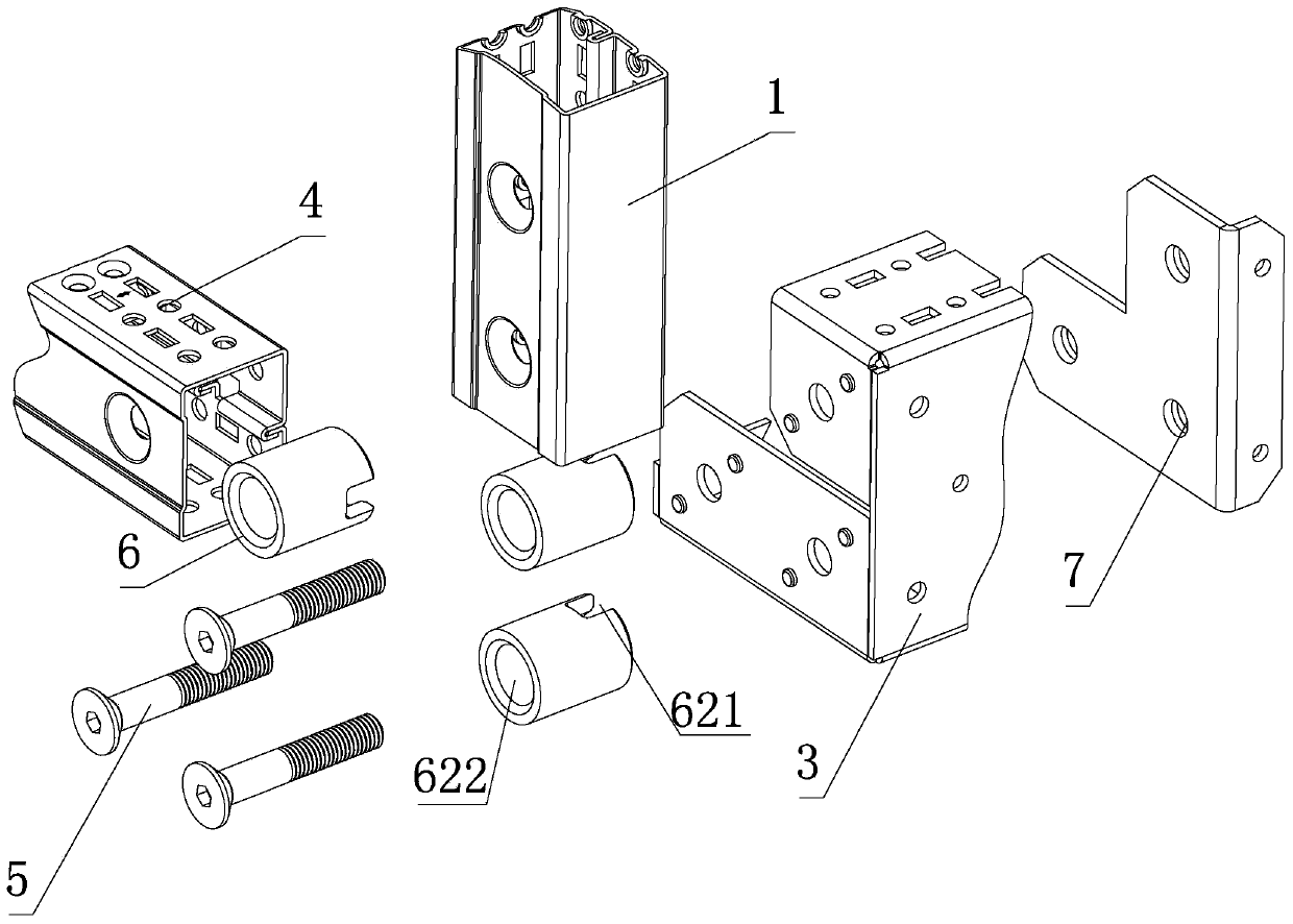
[0043] In this embodiment, the corner fastening device includes a corner connecting block 6 and a pressing plate 7 , the corner connecting block 6 is pre-assembled and fixed on the end of the closed profile 1 , and the corner connecting block 6 is formed by a connecting plate 61 and the support column 62 are assembled and connected, the connecting plate 61 is provided with a positioning hole 612 for fixing the support column 63, the end surface of the support column 63 is provided with a positioning step 623, and the positioning hole 612 and The positioning step 623 cooperates to connect the connecting plate 61 and the support column 62 into a whole, and the support column 61 is provided with a second fastening hole 622 matched with the column 1; The cross-section of the beam 3 is adapted.
[0044] Two sides of the connecting plate 61 are provided with reinforced bending edges 611 , and a plurality ...
Embodiment 3
[0047] Example 3, with reference to the attached Figure 1-4 , 10-11.
[0048] In this embodiment, the confronting reinforcing rib device 12-1 means that the sealing portion of the closed profile can be fixedly connected by flat welding or other fastening methods. Correspondingly, the corner support column 62 does not need to be Set aside slot 621.
[0049] Other implementations of this embodiment are the same as those of Embodiment 1.
PUM
 Abstract
Description
Claims
Application Information
 - R&D Engineer
- R&D Manager
- IP Professional
- Industry Leading Data Capabilities
- Powerful AI technology
- Patent DNA Extraction
Browse by: Latest US Patents, China's latest patents, Technical Efficacy Thesaurus, Application Domain, Technology Topic.
© 2024 PatSnap. All rights reserved.Legal|Privacy policy|Modern Slavery Act Transparency Statement|Sitemap