Telescopic valve handle

A valve handle and handle technology, applied in valve details, valve device, valve operation/release device, etc., can solve the problems of slow switching speed, small opening and closing torque of gate valve, and laborious switching, so as to speed up the switching speed and prevent The effect of level loosening and fast switching speed

Inactive Publication Date: 2017-06-27
天津市沃特斯众友阀门有限公司
View PDF0 Cites 2 Cited by
  • Summary
  • Abstract
  • Description
  • Claims
  • Application Information

AI Technical Summary

Problems solved by technology

[0002] Valves are the control components in the fluid conveying system. They have many functions such as cut-off, adjustment, and diversion. They are important components in industrial production. Industrial valves are mainly divided into gate valves, butterfly valves, and globe valves. These valves have different uses. Each has its advantages, but there are deficiencies when opening and closing the valve, such as the opening and closing torque of the gate valve is small, the opening and closing torque is labor-saving, but the switching speed is very slow, the opening and closing torque of the butterfly valve and the globe valve are large, and the opening and closing torque is laborious.
In addition, due to the limitation of production space, longer valve handles cannot be used normally
Therefore, the existing valve handle has the disadvantages of laborious switching, slow switching speed, inconvenient use, etc.

Method used


Image

  • Telescopic valve handle
  • Telescopic valve handle

Examples


Embodiment Construction

[0021] The present invention will be described in detail below in conjunction with the accompanying drawings.

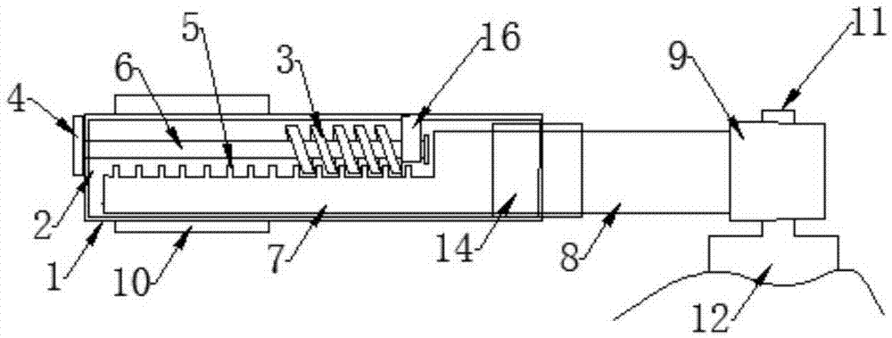
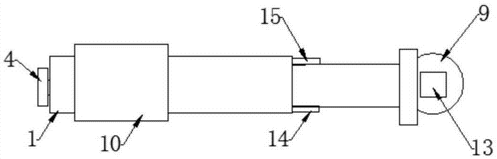
[0022] Such as figure 1 , figure 2 As shown, a telescopic valve handle of the present invention includes a fixed handle 1, a sliding cavity 2, a screw thread 3, a rotary knob 4, saw teeth 5, a screw shaft 6, a telescopic plate 7, a telescopic handle 8, a valve stem rotating plate 9, Grip cover 10, stem hole 13, front baffle 14, rear baffle 15, fixed block 16;

[0023] The fixed handle 1 is provided with a sliding chamber 2, and the sliding chamber 2 is provided with an axially rotatable screw shaft 6. The left end of the screw shaft 6 passes through the left side of the fixed handle 1 and is connected with the rotary knob 4. The fixed block 16 fixed on the top of the sliding cavity 2, the screw shaft 6 is provided with a screw thread 3;

[0024] A telescopic plate 7 is arranged below the screw shaft 6, and the upper surface of the telescopic plate 7 is provided w...


PUM


Abstract

The invention provides a retractable valve handle, which includes a fixed handle, a sliding cavity, a screw thread, a rotary knob, sawtooth, a screw shaft, a telescopic plate, a telescopic handle, a valve stem rotating plate, a valve stem hole, and a fixed block. Sliding chamber, the sliding chamber is provided with a helical shaft that can rotate axially, the left end of the helical shaft passes through the left side of the fixed handle and is connected with the rotary knob, the right side of the helical shaft passes through the fixed block fixed on the top of the sliding chamber, and the helical shaft is provided with There are threads, and there is an expansion plate under the screw shaft. The upper surface of the expansion plate is provided with serrations that engage with the thread. The right end of the expansion plate is fixedly connected with the expansion handle. The right end of the expansion handle is fixed with a valve stem rotating plate. stem hole. The invention has the beneficial effects of labor-saving switching, fast switching speed and convenient use.

Description

technical field [0001] The invention belongs to the technical field of valve equipment, in particular to a retractable valve handle. Background technique [0002] Valves are the control components in the fluid conveying system. They have many functions such as cut-off, adjustment, and diversion. They are important components in industrial production. Industrial valves are mainly divided into gate valves, butterfly valves, and globe valves. These valves have different uses. Each has its advantages, but there are deficiencies when opening and closing the valve. For example, the opening and closing torque of the gate valve is small, and the opening and closing torque is labor-saving, but the switching speed is very slow. The opening and closing torque of the butterfly valve and the globe valve are large, and the opening and closing torque is laborious. In addition, due to the limitation of production space, the longer valve handle cannot be used normally. Therefore, the existi...

Claims


Application Information

Patent Timeline
IPC IPC(8): F16K31/60
CPCF16K31/60
Inventor 王宝坤蔡春来
Owner 天津市沃特斯众友阀门有限公司
Why Eureka
Try Eureka