Efficient plate heat exchanger

A plate heat exchanger, high-efficiency technology, applied in the direction of heat exchanger types, indirect heat exchangers, heat exchange equipment, etc., can solve the problem of low heat exchange efficiency of heat exchangers, and achieve the goal of improving heat exchange efficiency and increasing flow rate Effect

Active Publication Date: 2017-06-27
JIANGYIN YALONG HEAT TRANSFER EQUIP CO LTD
View PDF6 Cites 0 Cited by
  • Summary
  • Abstract
  • Description
  • Claims
  • Application Information

AI Technical Summary

Problems solved by technology

[0004] In order to solve the problem of low heat exchange efficiency of current heat exchangers, the present invention provides a high-efficiency plate heat exchanger, which includes several sets of heat exchange plate groups stacked in sequence, and each set of heat exchange plate groups includes a first heat exchange plate group Plate 1 and second heat exchange plate 2, the first heat exchange plate 1 is covered on the second heat exchange plate 2, the first fluid channel 3 is formed between the first heat exchange plate 1 and the second heat exchange plate 2, adjacent The second fluid channel 4 is formed between the two sets of heat exchange plates; the two side edges of the first heat exchange plate 1 and the two side edges of the second heat exchange plate 2 form the first heat insulation channel 5, and the adjacent two sets of heat exchange A second heat-insulation channel 6 is formed between the edges on both sides of the plate, none of which is in communication with the fluid channel, and the first heat-insulation channel 5 and the second heat-insulation channel 6 on the same side form an insulating band

Method used


Image

  • Efficient plate heat exchanger
  • Efficient plate heat exchanger
  • Efficient plate heat exchanger

Examples


Embodiment Construction

[0015] All features disclosed in this specification, or steps in all methods or processes disclosed, may be combined in any manner, except for mutually exclusive features and / or steps.

[0016] Any feature disclosed in this specification, unless specifically stated, can be replaced by other alternative features that are equivalent or have similar purposes. That is, unless expressly stated otherwise, each feature is one example only of a series of equivalent or similar features.

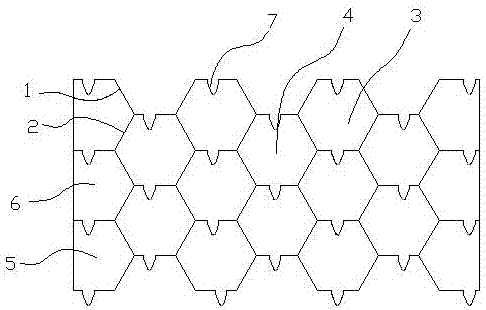
[0017] Such as figure 1 The high-efficiency plate heat exchanger shown includes several sets of heat exchange plate groups stacked in sequence, and each set of heat exchange plate groups includes a first heat exchange plate 1 and a second heat exchange plate 2, and the first heat exchange plate 1 is covered with On the second heat exchange plate 2, a first fluid channel 3 is formed between the first heat exchange plate 1 and the second heat exchange plate 2, and a second fluid channel 4 is formed bet...


PUM


Abstract

The invention discloses an efficient plate heat exchanger. The efficient plate heat exchanger comprises a plurality of sequentially overlapped heat exchange plate groups, and the heat exchange plate groups comprise first heat exchange plates (1) and second heat exchange plates (2); the first heat exchange plates (1) cover the second heat exchange plates (2); first fluid channels (3) are formed between the first heat exchange plates (1) and the second heat exchange plates (2); second fluid channels (4) are formed between the two adjacent heat exchange plate groups; first heat-insulated channels (5) are formed on the edges on the two sides of the first heat exchange plates (1) and on the edges on the two sides of the second heat exchange plates (2); second heat-insulated channels (6) are formed between the edges on the two sides of the two adjacent heat exchange plates; the heat-insulated channels do not communicate with the fluid channels; and the first heat-insulated channels (5) and the second heat-insulated channels (6) on the same side form heat insulation zones. According to the efficient plate heat exchanger, flow velocity of a fluid on the edge of the heat exchanger is increased, speed of temperature loss is decreased, temperature of the edge of the heat exchanger maintains relatively high, and heat exchange efficiency is greatly improved.

Description

technical field [0001] The invention relates to the field of heat exchangers, in particular to a high-efficiency plate heat exchanger. Background technique [0002] The heat exchanger is a device that transfers part of the heat of the hot fluid to the cold fluid, so that the temperature of the fluid reaches the index specified in the process flow. It is a general-purpose equipment in chemical, petroleum, power, food and many other industrial sectors. It is used in production occupy an important position in. [0003] Most of the plate heat exchangers are composed of several heat exchange plates. Two different fluid passages are formed between the three adjacent heat exchange plates to allow the fluid to exchange heat. Low, the temperature is also low, and the heat loss is faster, resulting in low heat transfer efficiency. Contents of the invention [0004] In order to solve the problem of low heat exchange efficiency of current heat exchangers, the present invention provi...

Claims


Application Information

Patent Timeline
Patent Type & Authority Applications(China)
IPC IPC(8): F28D9/00F28F3/08
CPCF28D9/0037F28F3/08Y02P20/10
Inventor 庞澄龙
Owner JIANGYIN YALONG HEAT TRANSFER EQUIP CO LTD
Why Eureka
Try Eureka