Anti-chopping shield with W-shaped shield body

A shield and anti-cutting technology, applied in the direction of defensive objects, can solve the problems of throwing liquid splash, lack of ability, damage, etc., and achieve the effect of avoiding splash, ensuring safety and good protection effect

Active Publication Date: 2017-06-27
BENGBU ZHIDA TECH CONSULTING CO LTD
View PDF5 Cites 3 Cited by
  • Summary
  • Abstract
  • Description
  • Claims
  • Application Information

AI Technical Summary

Problems solved by technology

In the face of such attacks, the shields of the prior art used by law enforcers can generally resist the direct damage of the throwing liquid to the shield holder, but since the surface of the shield is a plane or arc surface, the throwing liquid will splash irregularly on the shield surface , changing directions, throwing liquids can easily cause harm to other law enforcement officers in coordination
[0008] In addition, the shields of the prior art also appear to have insufficient ability when attacking criminals as weapons. Most of them are pure protective equipment, and it is urgent to enhance their attack capabilities to achieve both offensive and defensive effects.

Method used


Image

  • Anti-chopping shield with W-shaped shield body
  • Anti-chopping shield with W-shaped shield body
  • Anti-chopping shield with W-shaped shield body

Examples


Embodiment 1

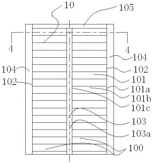
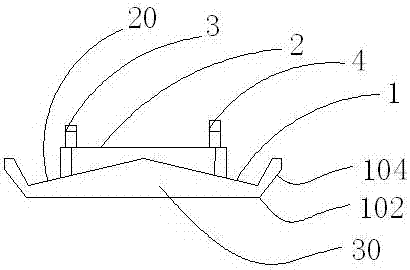
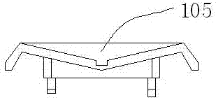
[0036] Embodiment 1: as Figure 1-4 As shown, a W-shaped shield is an anti-cut shield, which includes a shield body 1, a handle 4, a pad 2 and an elbow locking fixture 3, and the shield body 1 includes a shield body front 10 and a shield body back 20, the pad 2 is connected to the back 20 of the shield body, the handle 4 and the elbow locking fixture 3 pass through the pad 2 and connected to the shield body 1, wherein the shield body front 10 Including shield ridge 102, shield front 100, shield side 104 and shield bottom 103, the shield ridge 102 extends laterally to the shield bottom 103 to form the shield front 100, and the height of shield ridge 102 gradually decreases when it extends laterally, the definition of height here It is the distance from the front of the shield 100 to pad 2. The shield ridge 102 extends along the direction of the shield back 20 to form a shield side 104 , and the shield side 104 may also extend obliquely outward or inward along the direction of ...

Embodiment 2

[0046] Such as figure 1 and Figure 6 As shown, this embodiment provides another preferred technical solution for the structure of the second guide groove 106 on the basis of Embodiment 1, and what has been described in Embodiment 1 will not be repeated in this embodiment. Wherein, the shield bottom 103 further includes a second guide groove 106, and the second guide groove 106 is vertically arranged along the shield bottom axis 103a. The second guide groove 106 includes a groove opening 106a and a groove bottom 106b, the size of the groove opening 106a is smaller than the size of the groove bottom 106b, and the second guide groove 106 can be a convex groove or a dovetail groove or a pocket groove, or can be is a polygon slot. Compared with the situation in which the size of the groove opening 106a of the second guide groove described in the foregoing embodiment 1 is greater than or equal to the size of the groove bottom 106b, this technical solution is mainly for catching a...

Embodiment 3

[0048] Such as Figure 7-8 As shown, this embodiment provides another preferred technical solution for the shield ridge 102 on the basis of the first embodiment. The content already described in Embodiment 1 will not be repeated in this embodiment. Wherein, the shield ridge 102 and the protective plate 105 surface are provided with anti-cutting strips 107, and the shield body 1 also includes a shield head 30, and the surface of the shield head 30 is also provided with anti-cutting strips 107, and the anti-cutting strips 107 can pass through The prior art methods such as bonding or screw connection are connected with the corresponding parts, and the anti-cut strip 107 is made of flexible or semi-rigid material, such as high-strength rubber material, which can effectively resist cutting.


PUM


Abstract

The invention discloses an anti-chopping shield with a W-shaped shield body. The anti-chopping shield comprises the shield body, handheld handles, a protective pad, and elbow locking and fixing devices, wherein the shield body comprises a shield body front surface and a shield body back surface; the protective pad is connected with the shield body back surface; each handheld handle and the corresponding elbow locking and fixing device penetrate through the protective pad and are connected with the shield body; the shield body front surface comprises shield ridges, shield front surfaces, shield lateral surfaces and a shield bottom; the shield ridges transversely extend to the shield bottom to form the shield front surfaces, and height gradually decreases when the shield ridges transversely extend; the shield ridges extend along the direction of the shield body back surface to form the shield lateral surfaces; the shield ridges, the shield front surfaces and the shield lateral surfaces are in symmetrical arrangement along the axis of the shield bottom, and are integrated into the W-shaped shield body front surface; and an anti-chopping bar is arranged on the surface of each shield ridge. The shield can be used for defending against the attack of liquid, thrown objects, cutters and the like, and has offending and defending functions.

Description

technical field [0001] The invention relates to a shield, in particular to a police shield with anti-cutting function. Background technique [0002] Shields are an ancient defensive weapon. Soldiers holding shields can effectively block the enemy's weapons and protect their own lives. In ancient combat, whether in the history of China, ancient Greece or ancient Rome, the shield is a very important weapon for tactical use and has been developed to this day. Although the glory of the shield in military use no longer exists today, the shield has a new life in the field of modern police use. In the current atmosphere where the world pattern tends to be peaceful, large-scale wars are unlikely to occur, but individual criminal activities within the country frequently occur. Therefore, the personal safety issues faced by police officers are the first to bear the brunt. At this time, police shields It has played a very important role in the field of single police protection. [0...

Claims


Application Information

Patent Timeline
Patent Type & Authority Applications(China)
IPC IPC(8): F41H5/08
CPCF41H5/08
Inventor 曾国庆
Owner BENGBU ZHIDA TECH CONSULTING CO LTD
Why Eureka
Try Eureka