
Extremely-weak optical signal degree of polarization detection system and detection method based on same system

A detection system and polarization degree technology, applied in the field of extremely distant target detection and identification, can solve problems such as single information, and achieve the effect of breaking through the counting bottleneck

Inactive Publication Date: 2017-06-27
HARBIN INST OF TECH
View PDF3 Cites 9 Cited by
  • Summary
  • Abstract
  • Description
  • Claims
  • Application Information

AI Technical Summary

Problems solved by technology

[0004] The present invention is to solve the problem that when the existing laser radar detects extremely long-distance targets, the information is obtained in a single way, and the target cannot be effectively judged and identified. Now it provides a very weak optical signal polarization detection system and a detection method

Method used


Image

  • Extremely-weak optical signal degree of polarization detection system and detection method based on same system
  • Extremely-weak optical signal degree of polarization detection system and detection method based on same system
  • Extremely-weak optical signal degree of polarization detection system and detection method based on same system

Examples


specific Embodiment approach 1

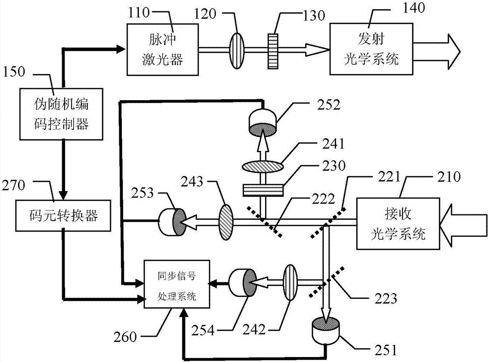
[0064] Specific implementation mode one: refer to figure 1 Describe this implementation mode in detail. A very weak optical signal polarization detection system described in this implementation mode includes: a transmitting unit and a receiving unit;

[0065] The transmitting part includes: a pulsed laser 110, a polarizer 120 of the transmitting part, a 1 / 4 wave plate 130 of the transmitting part, a transmitting optical system 140 and a pseudo-random code controller 150,

[0066] The code sequence signal output terminal of the pseudo-random code controller 150 is connected to the code sequence signal input terminal of the pulse laser 110, and the pulsed laser light emitted by the pulse laser 110 is transmitted to the transmitter through the polarizer 120 of the transmitting part and the 1 / 4 wave plate 130 of the transmitting part in sequence. The optical system 140, the transmitting optical system 140 collimates and expands the incident light and emits it to the target to be d...

specific Embodiment approach 2

[0074] Specific embodiment 2: This embodiment is a further description of a very weak optical signal polarization detection system described in specific embodiment 1. In this embodiment, the polarizing angle of the second polarizer 242 of the receiving part is 90° °, the polarizing angles of the No. 1 polarizer 241 and the No. 3 polarizer 243 of the receiving part are both 45°, and the azimuth angle of the 1 / 4 wave plate 230 of the receiving part is 0°.

specific Embodiment approach 3

[0075] Specific embodiment three: This embodiment is a further description of a very weak optical signal polarization detection system described in specific embodiment two. In this embodiment, the synchronous signal processing system 260 includes the following units:

[0076] Stokes parameter setting unit:

[0077] Let the Stokes parameter of the echo signal light collected by the receiving optical system 210 be:

[0078] (S 0 S 1 S 2 S 3 ) T

[0079] Among them, S 0 , S 1 , S 2 , S 3 are the four parameters of the normalized Stokes parameter,

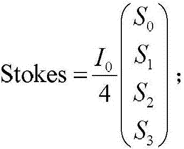
[0080] Because the echo signal light is divided into four paths by No. 1 optical splitter 221, No. 2 optical splitter 222 and No. 3 optical splitter 223, the total intensity of setting the echo signal light signal is 1 0 , then the intensity Stokes of each echo signal light Stokes parameter is:

[0081]

[0082] The corresponding light intensity acquisition unit of the detector:

[0083] The Stokes parameter Stokes1 ...


PUM


Abstract

The invention relates to an extremely-weak optical signal degree of polarization detection system and a detection method based on the same system, and relates to the technical field of laser radar. The invention aims to solve the problem that when the existing laser radar detects a very long distance target, the obtained information is single and the judgment and recognition of the target cannot be effectively performed. The extremely-weak optical signal degree of polarization detection system and the detection method based on the same system radiate the target with an optical signal subjected to polarization modulation, split the echo signal light into four ways, and use Gm-APD for performing photon counting. According to the counting result, the photon polarization information of the echo signal light is obtained, so as to achieve the purpose of identifying the target. The invention uses Gm-APD for photon counting, the response sensitivity has reached a single photon level, breaking the counting bottleneck of the traditional radar, and according to the response counting, an extremely weak signal polarization solution is achieved. The method and the system provided by the invention are applicable to long-distance target identification and detection and weak light optical detection of the single photon level.

Description

technical field [0001] The invention belongs to the technical field of laser radar, and in particular relates to the detection and recognition technology of extremely distant targets. Background technique [0002] For extremely distant targets, the echo signal light of the detection signal light is often extremely weak and has reached the single photon level. Ordinary light intensity detectors cannot respond to such weak signals. bottlenecks encountered. [0003] The current single-photon detection technology can only obtain the three-dimensional range image of the target, and the response sensitivity is limited. Only through the range image of the target to judge and identify the target, the information is too single, and often cannot effectively obtain the target polarization information, and thus cannot be effective To judge and identify the target. Contents of the invention [0004] The present invention is to solve the problem that when the existing laser radar dete...

Claims


Application Information

Patent Timeline
Patent Type & Authority Applications(China)
IPC IPC(8): G01S17/88
CPCG01S17/88
Inventor 张子静赵远张勇靳辰飞张建东岑龙柱李硕闫林玉
Owner HARBIN INST OF TECH
Learn More