
Passive sensor device for measuring shock wave energy based on combined aluminum honeycomb

A sensor device and passive measurement technology, which is applied in the field of measurement and detection, can solve problems such as cumbersome processing procedures, complex measurement systems, and difficult wiring, and achieve the effects of simple and intuitive results, high response sensitivity, and convenient layout and use

Active Publication Date: 2019-04-26
NAT UNIV OF DEFENSE TECH
View PDF5 Cites 16 Cited by
  • Summary
  • Abstract
  • Description
  • Claims
  • Application Information

AI Technical Summary

Problems solved by technology

[0008] The technical problem to be solved by the present invention is to provide a device that uses a combined aluminum honeycomb to make an energy-absorbing component to realize passive quantitative measurement of the local energy of the shock wave, and solve the problem of wiring difficulties in the current active measurement technology of the electric measurement active sensor. Interference and other problems; make up for the shortcomings of existing passive measurement technologies, which may require electrical measurement equipment to assist measurement, or the measurement system is complex, or the post-measurement processing procedures are cumbersome; it can be used for explosive explosions in standard shooting ranges, field shooting ranges, and other harsher environments The measurement of shock wave energy provides a new reference option for the measurement of shock wave parameters

Method used


Image

  • Passive sensor device for measuring shock wave energy based on combined aluminum honeycomb
  • Passive sensor device for measuring shock wave energy based on combined aluminum honeycomb
  • Passive sensor device for measuring shock wave energy based on combined aluminum honeycomb

Examples


Embodiment Construction

[0033] In order to facilitate those of ordinary skill in the art to understand and implement the patent of the present invention, the present invention will be further described in detail below in conjunction with the accompanying drawings and specific embodiments.

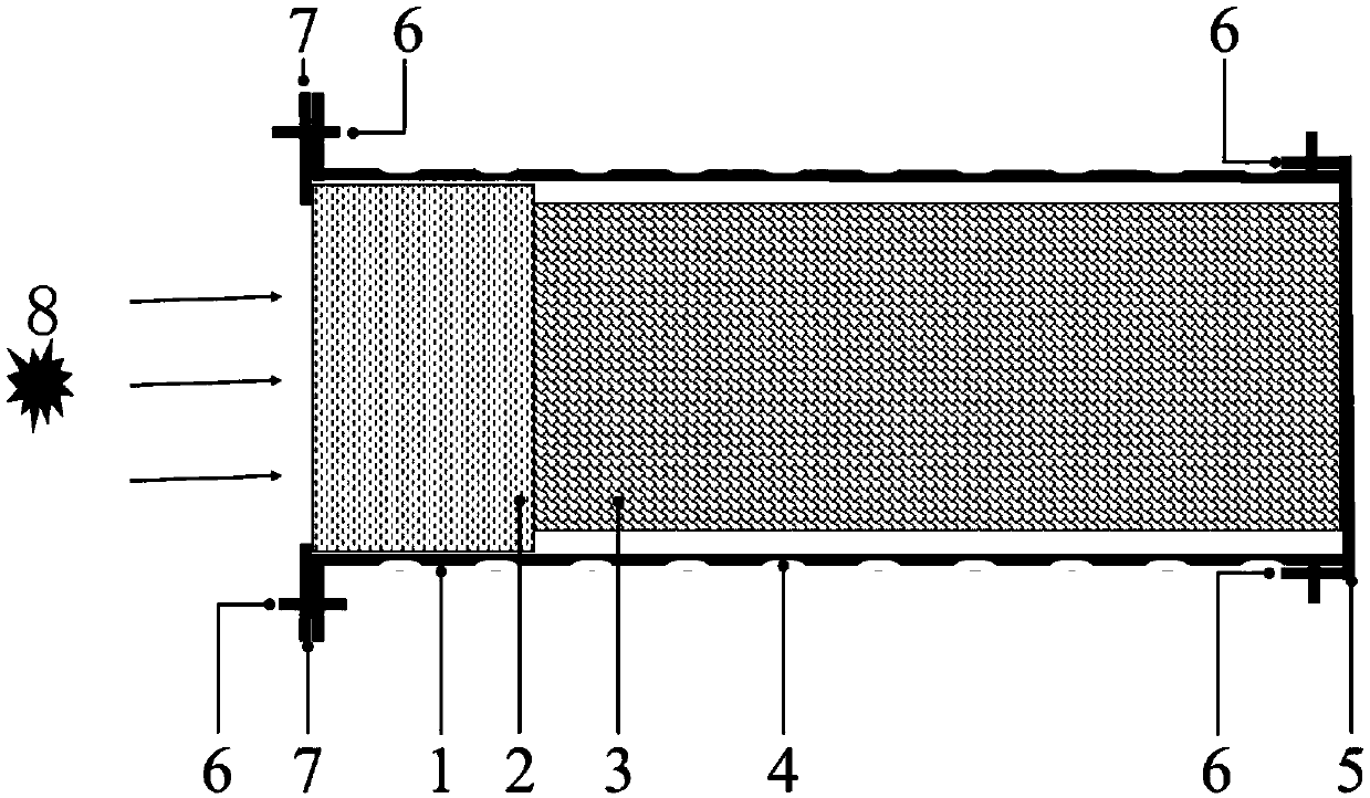
[0034] figure 1 It is a schematic diagram of the overall structure of the sensor for passively measuring shock wave energy provided by the present invention. Such as figure 1 shown.

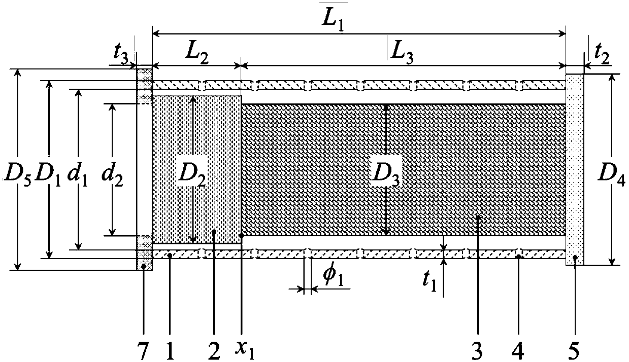
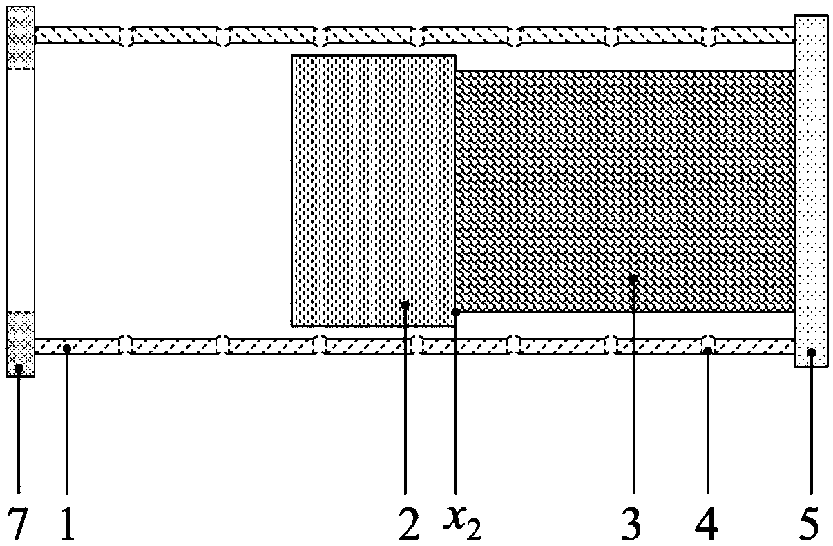
[0035] The present invention is composed of a packaging case 1, a driving slider 2, a combined aluminum honeycomb energy-absorbing component 3, a solid wall stop plate 5, a movable bolt 6, and a sealing retaining ring 7. The end of the present invention close to the explosion point 8 is the left end of the present invention, and the end of the present invention far away from the explosion point 8 is the right end. The driving slider 2 and the combined aluminum honeycomb energy-absorbing member 3 are located in the packaging casing...


PUM

PropertyMeasurementUnit
diameteraaaaaaaaaa
diameteraaaaaaaaaa
friction coefficientaaaaaaaaaa

Abstract

The invention discloses a passive sensor device for measuring shock wave energy based on a combined aluminum honeycomb, which consists of a packaging shell, a driving slide block, a combined aluminumhoneycomb energy absorbing element, a fixed wall stop plate, a moving bolt and a sealing baffle ring. And the driving slide block moves in the packaging shell under the action of the shock wave to compress the combined aluminum honeycomb energy absorbing element, and the combined aluminum honeycomb energy absorbing element generates plastic unrecoverable deformation. The shock wave energy acting on the driving slide block can be obtained by measuring the plastic deformation displacement on the combined aluminum honeycomb energy absorbing element caused by the driving slide block and utilizingthe relationship between the plastic deformation displacement and the absorbed energy. The combined aluminum honeycomb energy absorbing element has the advantages of simple structure, no need of powersupply, convenient arrangement and use, low cost and reusability, and the response sensitivity of the combined aluminum honeycomb energy absorbing element to lower shock waves is high, so that the technical problem that the shock wave energy is difficult to quantitatively test under partial severe environments can be solved.

Description

technical field [0001] The invention belongs to the field of measurement and detection, and in particular relates to a sensor for measuring shock wave parameters generated by an explosion, and more specifically relates to a passive sensor device for measuring the energy of an explosion shock wave by utilizing the energy absorption characteristics of materials. Background technique [0002] In the prior art, generally two methods of active measurement and passive measurement can be used to realize the measurement of parameters such as pressure, impulse and energy of the shock wave generated by explosive explosion. Active measurement mainly relies on various traditional electrical sensors. Although the electrical sensor measurement technology is relatively mature (there are various types of shock wave electrical measurement sensors on the market), due to the relatively complicated explosion test environment, traditional electrical sensors are used for active measurement. Sourc...

Claims


Application Information

Patent Timeline
Patent Type & Authority Applications(China)
IPC IPC(8): G01L5/14G01L1/06
Inventor 林玉亮李翔城孟祎梁民族李志斌陈荣李翔宇卢芳云
Owner NAT UNIV OF DEFENSE TECH
Learn More