
Optical unit with shake correction function and method of manufacturing the same

A shake correction, optical unit technology, applied in the direction of optical components, optical, electrical components, etc., can solve the problem of not being able to form a stop mechanism that limits the swing range of the movable body, and achieve the effects of preventing excessive swing, efficient manufacturing, and downsizing

Active Publication Date: 2020-07-14
SANKYO SEIKI MFG CO LTD
View PDF6 Cites 0 Cited by
  • Summary
  • Abstract
  • Description
  • Claims
  • Application Information

AI Technical Summary

Problems solved by technology

However, in the case of adopting the above-mentioned structure, there is a problem that a stopper mechanism for restricting the swing range of the movable body cannot be constituted because there is no space for installing the swing restricting member in the middle of the optical axis direction of the fixed body.

Method used


Image

  • Optical unit with shake correction function and method of manufacturing the same
  • Optical unit with shake correction function and method of manufacturing the same
  • Optical unit with shake correction function and method of manufacturing the same

Examples


Embodiment Construction

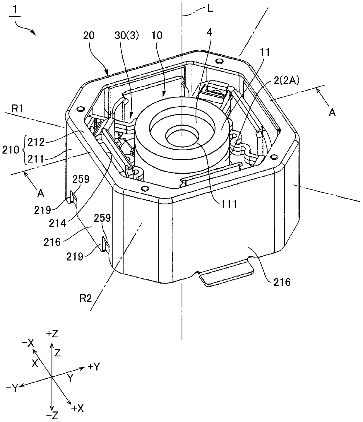
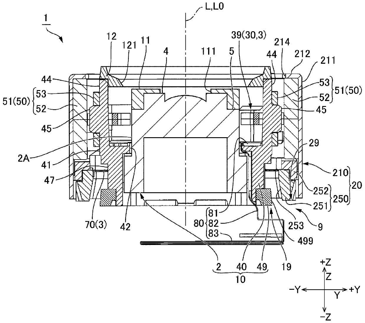
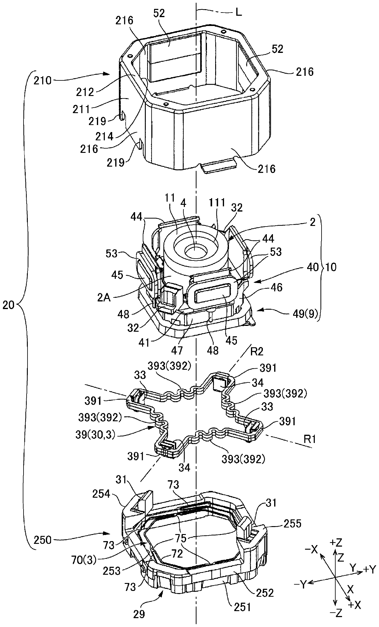
[0072] An optical unit 1 with a shake correction function to which the present invention is applied will be described with reference to the drawings. In the following description, the three axes of XYZ are mutually orthogonal directions, +X indicates one side of the X-axis direction, -X indicates the other side of the X-axis direction, and +Y indicates one side of the Y-axis direction , Use -Y to indicate the other side of the Y-axis direction, use +Z to indicate one side of the Z-axis direction, and use -Z to indicate the other side of the Z-axis direction. The Z-axis direction is the central axis L of the optical unit 1 with a shake correction function. The direction of the central axis L is the direction of the optical axis of the optical module 2 installed in the optical unit 1 with shake correction function. The −Z direction is a direction toward the image side of the optical axis direction, and the +Z direction is a direction toward the object side of the optical axis d...


PUM


Abstract

The present invention provides an optical unit with a shake correction function and a manufacturing method thereof, which can constitute a stopper mechanism that limits the swing range of a movable body even when one side of the fixed body in the optical axis direction is set as an open end . An optical unit (1) with a shake correction function has: a movable body (10) having a holder (40) holding an optical module (2) inside; and the movable body (10) is supported by a support mechanism (3) Be the fixed body (20) that can swing. One end in the optical axis direction of the fixed body (20) is an open end (29). The movable body (10) has a protrusion (19) protruding from an open end (29) to one side in the direction of the optical axis. The fixed body (20) has a swing limiting portion (253) at an open end (29) that abuts on the protruding portion (19) when the movable body (10) swings to limit the swing range of the movable body (10).

Description

technical field [0001] The invention relates to an optical unit with shake correction function and a manufacturing method thereof. Background technique [0002] In order to suppress disturbance of captured images due to hand shake or vibration, an optical unit with a shake correction function that can correct shake by swinging a movable body holding an optical module with a holder has been proposed. In the above-mentioned optical unit with a shake correction function, a base plate is generally provided on a fixed body, and the base plate covers a movable body (for example, Refer to Patent Document 1). In addition, in the optical unit with a shake correction function described in Patent Document 1, a structure is adopted in which a swing restricting member is provided between a case covering the movable body and a bottom plate, and when the swing restricting member restricts the swing of the movable body, swing range. [0003] Patent Document 1: Japanese Patent Laid-Open N...

Claims


Application Information

Patent Timeline
Patent Type & Authority Patents(China)
IPC IPC(8): G03B5/00G02B7/02G02B27/64H04N5/225H04N5/232
CPCG02B7/023G02B27/644G03B5/00G03B2205/0007H04N23/57H04N23/687G02B27/646G02B27/64G02B7/02
Inventor 须江猛南泽伸司
Owner SANKYO SEIKI MFG CO LTD
Learn More