
A valve handle punching and marking device

A valve handle and punching technology, which is applied in the field of valve processing, can solve the problems of large manual investment, etc., and achieve the effect of convenient operation and high degree of automation

Active Publication Date: 2019-05-24
重庆新锐科技服务有限公司
View PDF6 Cites 0 Cited by
  • Summary
  • Abstract
  • Description
  • Claims
  • Application Information

AI Technical Summary

Problems solved by technology

[0004] The present invention intends to provide a valve handle punching and marking device to solve the problem that in the traditional handle processing process, the forming of the processing groove and the marking process are carried out separately, the worker has to carry the handle repeatedly, and the problem of large manual investment

Method used


Image

  • A valve handle punching and marking device
  • A valve handle punching and marking device

Examples


Embodiment Construction

[0018] The present invention will be described in further detail below by means of specific embodiments:

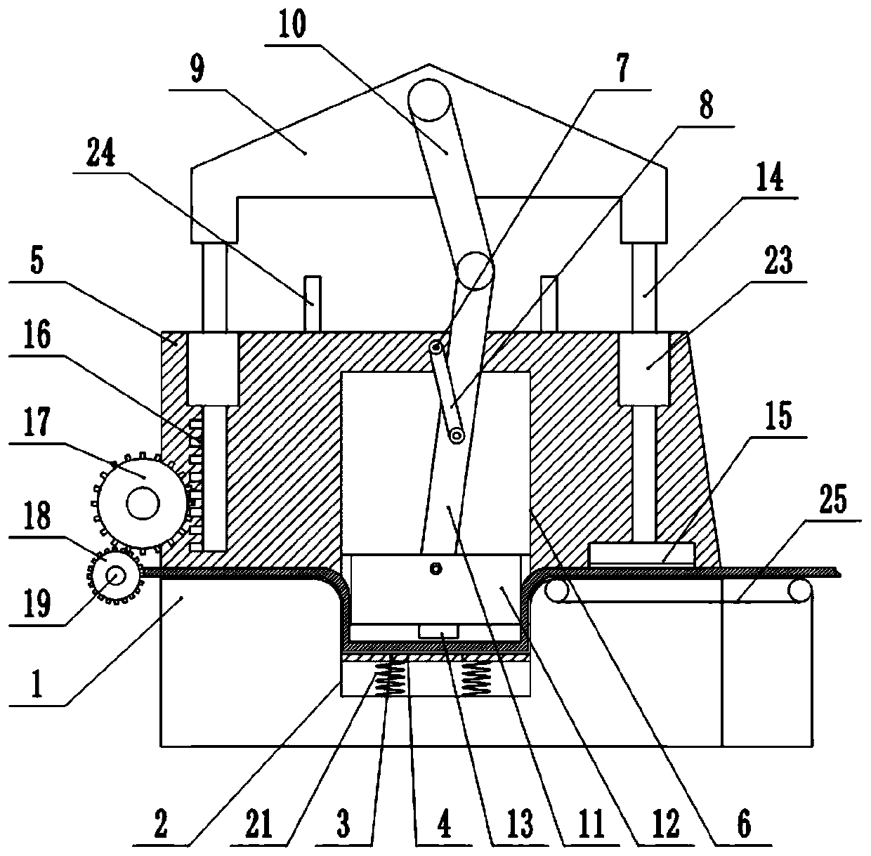
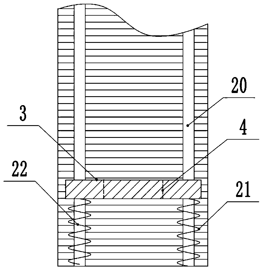
[0019] The reference signs in the accompanying drawings of the description include: marking table 1, punching groove 2, punching plate 3, punching hole 4, support plate 5, processing groove 6, driving shaft 7, driving rod 8, driving plate 9, first Connecting rod 10, second connecting rod 11, stamping block 12, bump 13, sliding rod 14, printing head 15, rack 16, first gear 17, second gear 18, grinding roller 19, chute 20, the first A spring 21, a second spring 22, a limit ring 23, a limit rod 24, and a conveyor belt 25.

[0020] The embodiment is basically as figure 1 Shown: a valve handle punching and marking device, including a frame and a marking table 1, a conveyor belt 25 is provided on one side of the printing table 1, and a stepping motor is connected to the conveyor belt 25, and a punching machine is provided on the printing table 1. Hole slot 2, rounded corners ...


PUM


Abstract

The invention relates to a punching and labeling device for a valve handle. The punching and labeling device for the valve handle comprises a machine frame and a labeling platform, wherein a punchinggroove is formed in the labeling platform and internally provided with a punching plate, and a punching hole is formed in the middle of the punching plate; the labeling platform is fixedly connected with a supporting plate; the supporting plate is provided with a machining groove; the upper portion of the machining groove is rotationally connected with a driving shaft; the driving shaft is fixedlyconnected with a driving rod; a driving plate is arranged above the supporting plate and rotationally connected with a first connecting rod; the first connecting rod is rotationally connected with asecond connecting rod; the other end of the second connecting rod is rotationally connected with a punching block; the punching block is connected in the machining groove in a sliding mode; a convex block is arranged at the bottom of the punching block and is opposite to the punching hole; the end, far away from the driving shaft, of the driving rod is rotationally connected to the second connecting rod; sliding rods are fixedly connected with the two ends of the driving plate; a labeling head is arranged at the bottom of one sliding rod, and the other sliding rod is fixedly connected with a rack; the rack is engaged with a gear; and the gear is coaxially and fixedly connected with a grinding roller. The punching and labeling device for the valve handle can carry out punching and labelingprocesses at the same time, and reduces the manual conveying work.

Description

technical field [0001] The invention relates to the field of valve processing, in particular to a punching and labeling device for a valve handle. Background technique [0002] A valve is a device used to control the direction, pressure, and flow of a fluid in a fluid system. A valve is a device that makes or stops the flow of media (liquid, gas, powder) in piping and equipment and controls its flow. Valves can be used to control the flow of various types of fluids such as air, water, steam, various corrosive media, mud, oil, liquid metal and radioactive media. The valve is a control component in the pipeline fluid delivery system. It is used to change the passage section and the flow direction of the medium, and has the functions of diversion, cut-off, throttling, check, diversion or overflow relief. [0003] The structure of the valve includes actuators, positioners, accessories and other accessories, such as: valve body, valve core, valve stem, handle, first wheel, valv...

Claims


Application Information

Patent Timeline
Patent Type & Authority Patents(China)
IPC IPC(8): B21D28/26B21C51/00B21D43/12B21D45/06B24B9/04
CPCB21C51/005B21D28/26B21D43/12B21D45/006B24B9/04
Inventor 罗贵良
Owner 重庆新锐科技服务有限公司
Learn More