
Electromechanical Servo Brake

A servo brake, electromechanical servo technology, applied in the direction of brakes, brake transmission devices, hydraulic brake transmission devices, etc., can solve problems such as wear and loss of freedom

Active Publication Date: 2018-11-06
ROBERT BOSCH GMBH
View PDF7 Cites 0 Cited by
  • Summary
  • Abstract
  • Description
  • Claims
  • Application Information

AI Technical Summary

Problems solved by technology

The pushrod 47 is therefore stationary and has no degrees of freedom along the axis (xx) of the servo brake, so that the transverse component of the thrust acting on the pushrod 47 through the auxiliary piston 20 appears as a transverse force of the stress acting on the main piston 49 weight, which causes its irregular wear

Method used


Image

  • Electromechanical Servo Brake
  • Electromechanical Servo Brake
  • Electromechanical Servo Brake

Examples


Embodiment Construction

[0022] To simplify the description, by convention, such as figure 1 As shown, the front (AV) of the servo brake is on the side of the tandem master cylinder and the rear (AR) is on the side of the lever actuated by the brake pedal.

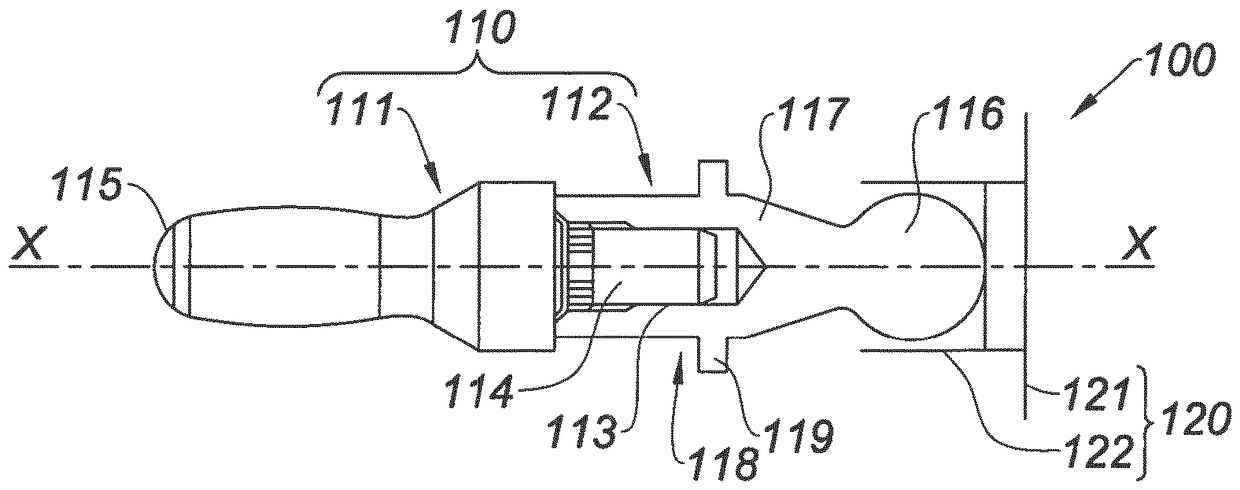
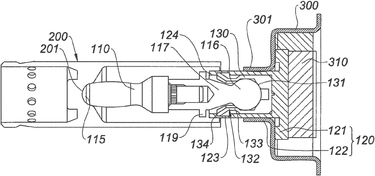
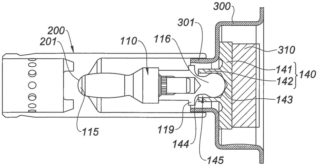
[0023] figure 2 A thrust unit 100 of a servo brake according to the invention is shown very schematically for transmitting the thrust of the auxiliary piston to the main piston. The thrust unit 100 comprises a push rod 110 and a bearing 120 which receives one end of the push rod and bears against the auxiliary piston, while the other end of the push rod bears in the coupelle of the main piston. The push rod 110 is made in two parts, where the front part 111 and the rear part 112 are assembled together by a tight fit. A section of the front part 111 is not shown, but a section of the rear part 112 is shown.

[0024] The rear part 112 has a cylindrical groove 113 for positively fitting the main shaft 114 of the front part 111 and constitutes a c...


PUM


Abstract

A servo brake includes a thrust unit connecting a servo-piston to a primary piston in an actuation direction. The thrust unit includes a plunger with a front end in the form of a spherical cap and pressed in a cup of the primary piston and a rear end that includes a ball joint. A bearing has a base pressed on a reaction disc and a sleeve that receives the ball joint of the plunger.

Description

technical field [0001] The invention relates to an electromechanical servo brake comprising a master piston of a master cylinder which is pushed in its actuation direction by a push rod which itself bears against an auxiliary piston. Background technique [0002] In electromechanical servobrakes, the main piston is moved by a pushrod, as in vacuum servobrakes, more precisely, in vacuum servobrakes, the pushrod is formed by a rod connected to a piston-form base via a reaction disc It rests on an auxiliary piston which is actuated by a pneumatically working brake force booster or by an electric motor which drives this piston by a rack transmission. [0003] Where the auxiliary piston is connected to the pneumatic piston, the assembly is mounted relatively loosely with sufficient degrees of freedom to induce no transverse force component on the main piston, but only a longitudinal force. [0004] In the case of an electromechanical servo brake, the connection of the auxiliary ...

Claims


Application Information

Patent Timeline
Patent Type & Authority Patents(China)
IPC IPC(8): B60T13/74B60T11/18
CPCB60T11/18B60T13/575B60T13/745
Inventor 志波正贵L.吕利耶A.奥古斯特
Owner ROBERT BOSCH GMBH
Learn More