
A Dense Array Antenna with Blind Insertion Structure

An array antenna and blind insertion technology, which is applied in the directions of separately powered antenna arrays, specific array feeding systems, antennas, etc., can solve the problems that dual-polarized multi-port base station antennas cannot adapt, and achieve the purpose of improving mobile communication capacity and optimizing System performance and the effect of improving spectrum resource efficiency

Active Publication Date: 2020-07-10
WUHAN HONGXIN TELECOMM TECH CO LTD
View PDF5 Cites 0 Cited by
  • Summary
  • Abstract
  • Description
  • Claims
  • Application Information

AI Technical Summary

Problems solved by technology

However, in the 5G communication era, technical requirements such as large data traffic, high speed, and low latency have become the norm, and traditional dual-polarized multi-port base station antennas can no longer meet the requirements of technological development and evolution.

Method used


Image

  • A Dense Array Antenna with Blind Insertion Structure
  • A Dense Array Antenna with Blind Insertion Structure
  • A Dense Array Antenna with Blind Insertion Structure

Examples


Embodiment Construction

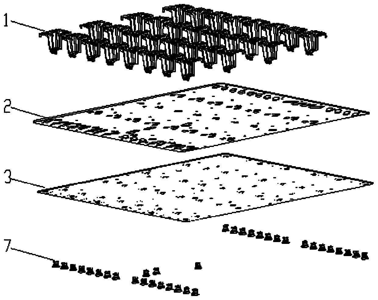
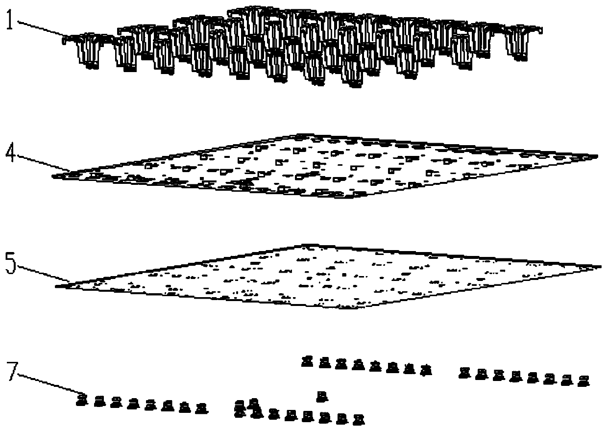
[0036] The present invention consists of a radiation oscillator part (1), a reflection plate A (2), a coupling feed network board A (3), a reflection plate B (4), a coupling feed network board B (5) and a calibration combination board C ( 6) Composition, in which the coupling feed network board A (3), the coupling feed network board B (5) and the calibration combination board C (6) are connected with the blind plug RF connector A (7) and the blind plug RF connector B ( 8) The plug-in connection is integrated into a whole, and the electrical characteristics of the coupling calibration network are designed to realize precise control of the amplitude and phase of each pair of vibrators, thereby realizing a dense array antenna with a blind-mating structure.

[0037] The present invention will be described in more detail below in conjunction with the accompanying drawings and examples.

[0038] The present invention proposes a dense array antenna for a 5G mobile communication syste...


PUM


Abstract

The invention relates to a dense array antenna having a blind insertion structure. The dense array antenna includes a radiation oscillator part, coupling feed network boards and a calibration combiner board part. The calibration combiner board is connected with the two feed network boards through blind insertion RF connectors into a complete feed network. The 3D beam shaping capabilities are gained. Multi-directional beam shaping can be achieved. The wireless communication system capacity can be greatly enhanced to achieve optimal system performance. Thus, operators are assisted in maximizing the use of existing sites and spectrum resources to ensure excellent performance of mobile communications.

Description

technical field [0001] The invention relates to a device used in the field of mobile communication, which is a dense array antenna with a blind-mating structure, more specifically, a dense array antenna connected by a blind-mating joint. Background technique [0002] With the continuous development of my country's mobile communication industry, research on the fifth generation mobile communication system (5G) has begun. The 5G mobile communication system requires greater communication capacity and higher wireless spectrum efficiency. The base station antenna needs to support 3D beamforming and more powerful MIMO functions. [0003] For improving mobile communication capacity, the conventional method is to use multi-port antennas of base stations with polarization diversity technology, which can reduce multipath fading and improve link stability, and use multi-port MIMO technology to further increase mobile communication capacity. However, in the 5G communication era, techni...

Claims


Application Information

Patent Timeline
Patent Type & Authority Patents(China)
IPC IPC(8): H01Q1/50H01Q1/38H01Q21/00H01Q21/06H01Q15/14
CPCH01Q1/38H01Q1/50H01Q15/14H01Q21/0025H01Q21/061
Inventor 俞思捷丁勇丁晋凯袁鹏亮
Owner WUHAN HONGXIN TELECOMM TECH CO LTD
Learn More