Parallel clamping mechanism

A clamping mechanism and clamping piece technology, applied in workpiece clamping devices, manufacturing tools, etc., can solve the problems of poor clamping effect, large occupied volume, and poor clamping mechanism accuracy, and achieve simple structure and high precision. High, good clamping effect

Active Publication Date: 2017-06-30
SUZHOU SECOTE PRECISION ELECTRONICS CO LTD
View PDF6 Cites 2 Cited by
  • Summary
  • Abstract
  • Description
  • Claims
  • Application Information

AI Technical Summary

Problems solved by technology

However, the accuracy of the clamping mechanism of this structure is poor, and it is easy to cause problems such as the product is not clamped or the clamping transition causes the product to be easily damaged, the clamping effect is poor, and the volume is large.

Method used


Image

  • Parallel clamping mechanism
  • Parallel clamping mechanism
  • Parallel clamping mechanism

Examples


Embodiment 1

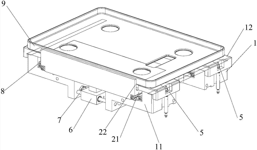
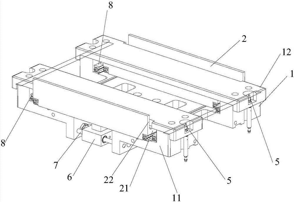
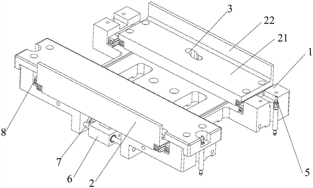
[0030] This preferred embodiment provides a parallel clamping mechanism, such as Figure 1 to Figure 4 As shown, the parallel clamping mechanism is a kind of parallel clamping mechanism, including a base 1, the base 1 includes a first side 11 and a second side 12 oppositely arranged, and the first side 11 is provided with a clamping assembly, a second An auxiliary clamping structure is provided on the two sides; the auxiliary clamping structure has the same structure as the clamping assembly; the clamping assembly includes a power device and a clamping part 2 slidingly arranged on the base 1, and the power device and the clamping part 2 One of them is provided with an arc-shaped chute 3, and the other is provided with a driving slider 4 that is slidably fitted in the arc-shaped chute 3, and the power unit can drive the driving slider 4 or the arc-shaped chute 3 arranged on the power unit Make a linear movement along the length direction of the base 1 to drive the clamping part...


PUM


Abstract

The invention discloses a parallel clamping mechanism and belongs to the technical field of clamping equipment. The parallel clamping mechanism is designed for solving the problems that existing devices are poor in clamping effect, large in size and the like. The parallel clamping mechanism comprises a base. The base comprises a first side edge and a second side edge which are arranged oppositely. A clamping assembly is arranged on the first side edge and an auxiliary clamping structure is arranged on the second side edge. The clamping assembly comprises a power device and a clamping part arranged on the base in a sliding mode. An arc-shaped sliding groove is formed in the clamping part, and a driving sliding block in sliding fit with the interior of the arc-shaped sliding groove is arranged on the power device. The power device can drive the driving sliding block to conduct linear movement in the length direction of the base, so that the clamping part is driven to slide on the base in the width direction of the base. According to the parallel clamping mechanism, the position of the clamping part can be determined by controlling the position of the driving sliding block in the arc-shaped sliding groove, and thus clamping force is adjusted, control precision is high, and the clamping effect is good.

Description

technical field [0001] The invention relates to the technical field of clamping equipment, in particular to a parallel clamping mechanism. Background technique [0002] During the processing and testing of products, especially electronic products, electronic products need to be clamped. For example, in the process of transporting and processing products through belts, the products need to be clamped, so as to realize the automatic production of products. [0003] However, the current clamping mechanism for electronic products usually includes a base for supporting the electronic product. Motors or cylinders are respectively arranged on both sides of the base, and the clamping parts are directly driven by the motor or cylinder to clamp the product. However, the accuracy of the clamping mechanism of this structure is poor, and it is easy to cause problems such as the product is not clamped or the product is easily damaged due to the transition of clamping, the clamping effect...

Claims


Application Information

Patent Timeline
Patent Type & Authority Applications(China)
IPC IPC(8): B25B11/00
CPCB25B11/00
Inventor 孙丰
Owner SUZHOU SECOTE PRECISION ELECTRONICS CO LTD
Why Eureka
Try Eureka