New energy charging pile and charging gun head device

A charging pile and new energy technology, applied in charging stations, electric vehicle charging technology, electric vehicles, etc., can solve problems such as lack of safety protection devices, safety accidents, casualties, etc., and achieve automatic locking of power supply connections, convenient operation, and isolation The effect of conductive contacts

Inactive Publication Date: 2017-06-30
XIAOGAN BUJI ELECTRONICS COMMERCE CO LTD
View PDF0 Cites 23 Cited by
  • Summary
  • Abstract
  • Description
  • Claims
  • Application Information

AI Technical Summary

Problems solved by technology

The input end of the charging pile is directly connected to the AC power grid, and the output end is equipped with a charging connector for charging the electric vehicle. During the charging process of the electric vehicle by the existing charging pile, the charging gun is easy to loosen, which will cause a safety accident. Causing

Method used


Image

  • New energy charging pile and charging gun head device
  • New energy charging pile and charging gun head device
  • New energy charging pile and charging gun head device

Examples


Embodiment Construction

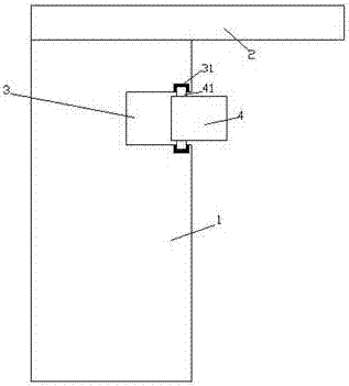
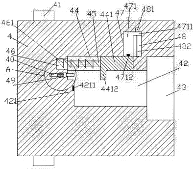
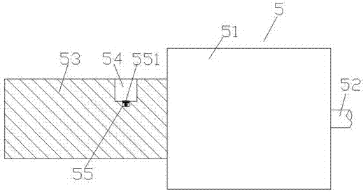
[0025] Such as Figure 1-Figure 6 As shown, a new energy charging pile and a charging gun head device of the present invention include a pile body 1 and a charging gun head 5, the pile body 1 is provided with a recessed groove 3, and the recessed groove 3 is provided with Charging mechanism 4, an insertion groove 42 is provided at the middle position inside the charging mechanism 4, and an embedding groove 43 communicating with the right side end of the insertion groove 42 is provided in the right end surface of the charging mechanism 4, and the insertion groove 42 A first sliding groove 44 is provided in the upper left inner wall, first guide grooves 45 are symmetrically arranged on the front and rear inner walls of the first sliding groove 44, and a sunken groove 46 is arranged in the left inner wall of the first sliding groove 44, The charging mechanism 4 above the right side of the first sliding slot 44 is provided with a second sliding slot 47 whose bottom communicates wi...


PUM


Abstract

The invention discloses a new energy charging pile and a charging gun head device. The new energy charging pile comprises a pile body and a charging gun head. An embedding groove is provided in the pile body, and a charging mechanism is arranged in the groove. An inserting groove is formed at the middle position within the charging mechanism. A scarfing groove communicated with the right end of the inserting groove is formed in the right end face of the charging mechanism. A first sliding groove is formed in the inner wall of the left upper side of the inserting groove. First guide grooves are symmetrically arranged in front and rear inner walls within the first sliding groove. A sunken groove is formed in the left inner wall of the first sliding groove. A second sliding groove with the bottom communicated with the first sliding groove is formed in the charging mechanism located above the right side of the first sliding groove. A second guide groove is provided in the charging mechanism at the right side of the second sliding groove. A recessed groove is provided in an upper position of the left inner wall of the inserting groove. A sliding cavity is arranged in the wall body of the charging mechanism on the left side of the recessed groove, and a sliding hole arranged extending toward the wall bodies of the charging mechanism on the left and right sides is provided in the sliding cavity. A first sliding block is arranged in the first sliding groove, and a convex plate extending into the inserting groove is arranged at the left edge of the bottom of the first sliding block. The new energy charging pile is simple in structure, and capable of automatic locking and power supply connection, and high in safety.

Description

technical field [0001] The invention relates to the technical field of new energy charging, in particular to a new energy charging pile and a charging gun head device. Background technique [0002] As a green transportation tool with broad development prospects, electric vehicles will be popularized at an extremely fast speed, and the future market prospects are also extremely huge. However, electric vehicles need to be charged through charging piles before they can continue to be used. Charging piles are installed in parking lots or charging stations of public buildings and residential areas, and can charge various types of electric vehicles according to different voltage levels. The input end of the charging pile is directly connected to the AC power grid, and the output end is equipped with a charging connector for charging the electric vehicle. During the charging process of the electric vehicle by the existing charging pile, the charging gun is easy to loosen, which wi...

Claims


Application Information

Patent Timeline
IPC IPC(8): B60L11/18
CPCB60L53/31Y02T10/70Y02T10/7072Y02T90/12
Inventor 梁敏华
Owner XIAOGAN BUJI ELECTRONICS COMMERCE CO LTD
Why Eureka
Try Eureka