Multifunctional railway line-crossing swing bridge closure construction formwork and construction method thereof

A railway line, multi-functional technology, applied in the field of formwork application, can solve the problems of steel shell becoming a hidden danger in the later stage, existing line damage, and difficulty in hanging baskets retreating.

Active Publication Date: 2017-06-30
CCTEB INFRASTRUCTURE CONSTR CO LTD +1
View PDF4 Cites 3 Cited by
  • Summary
  • Abstract
  • Description
  • Claims
  • Application Information

AI Technical Summary

Problems solved by technology

[0002] The mid-span closing hanger across the business line generally adopts a hanging basket, which is difficult to retreat. The steel shell of the steel shell method may become a hidden danger in the later stage. At present, more hangers are used. The conventional hanger installation adopts large-scale mechanical auxiliary installation, but the cross-business line It is difficult to realize the auxiliary installation of large-scale equipment w

Method used


Image

  • Multifunctional railway line-crossing swing bridge closure construction formwork and construction method thereof
  • Multifunctional railway line-crossing swing bridge closure construction formwork and construction method thereof
  • Multifunctional railway line-crossing swing bridge closure construction formwork and construction method thereof

Examples


Embodiment 1

[0031] Used in lifting rails, the steps are as follows:

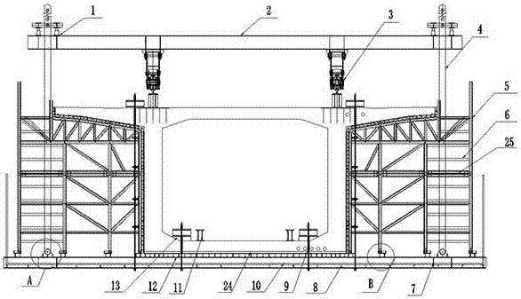
[0032] Step A. According to the functional requirements, special design and processing are required. The bottom of the lateral steel formwork 25 that can be moved laterally is welded to the reinforcing column 17, and the original column of the lateral steel formwork 25 is jointly stressed, and the rolling bearing 20 is connected to the original column of the formwork through the pin. Connected with the reinforcement column 17;

[0033] Step B, before the construction of the mid-span closure, install the lateral steel formwork 25 that can move laterally on the traveling equipment, and use the limit pins 18 to pin and fix the lateral steel formwork 25. A limit stop 22 of hard wood is set on the limit bottom plate 23 at the bottom, and a walking pair tie rod 24 is installed before walking;

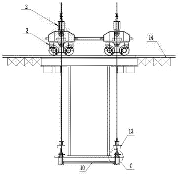
[0034] Step C, utilize the movable hoisting equipment to transport the hanger section hanger and the lateral steel formwork 25 to th...

Embodiment 2

[0040] Applied in lifting cement board, the steps are as follows:

[0041] Step A. According to the functional requirements, special design and processing are required. The bottom of the lateral steel formwork 25 that can be moved laterally is welded to the reinforcing column 17, and the original column of the lateral steel formwork 25 is jointly stressed, and the rolling bearing 20 is connected to the original column of the formwork through the pin. Connected with the reinforcement column 17;

[0042]Step B, before the construction of the mid-span closure, install the lateral steel formwork 25 that can move laterally on the traveling equipment, and use the limit pins 18 to pin and fix the lateral steel formwork 25. A limit stop 22 of hard wood is set on the limit bottom plate 23 at the bottom, and a walking pair tie rod 24 is installed before walking;

[0043] Step C, utilize the movable hoisting equipment to transport the hanger section hanger and the lateral steel formwork...


PUM


Abstract

The invention discloses a multifunctional railway line-crossing swing bridge closure construction formwork and a construction method thereof. The method comprises the following steps: (A) requiring special design and processing according to the function requirements; (B) before midspan closure construction, arranging a lateral steel form capable of transversely moving on running equipment, carrying out pin-connected fixing on the lateral steel form by using a limiting pin and arranging a walking tie rod before walking; (C) transporting a closure segment hanging bracket and the lateral steel form to a closure segment position by using walkable hoisting equipment; (D) dismantling a walking tie rod, removing the limiting pin and taking out a limiting stop block; (E) arranging the lateral steel form; (F) completing midspan closure concrete casting and maintenance, carrying out vertical demolding, applying horizontal action force to the lateral steel form and demolding in the horizontal direction; and (G) moving the lateral steel form to the design position, dismantling the lateral steel form and thus completing closure segment construction. The potential safety hazard of existing line-crossing closure construction can be effectively reduced and the construction efficiency is improved.

Description

technical field [0001] The invention relates to a formwork and a construction method thereof, in particular to a multifunctional cross-railway horizontally swivel bridge closing construction formwork and a construction method thereof, belonging to the technical field of formwork application. Background technique [0002] Generally, it is difficult to use hanging baskets for the mid-span closure hangers across the business line. The steel shell of the steel shell method may become a hidden danger in the later stage. At present, more hangers are used. The conventional hanger installation adopts large-scale mechanical auxiliary installation, but the cross-business line It is difficult to realize the auxiliary installation of large-scale equipment. After the lateral steel formwork and the protective chassis are transported to the design position by the walking system, the adjustment of the lateral steel formwork becomes a construction problem. Generally, jacks are used to direct...

Claims


Application Information

Patent Timeline
IPC IPC(8): E01D21/00
CPCE01D21/00
Inventor 谢小飞张月邈周胜强解鑫鹏苏祥瑞鲁帅
Owner CCTEB INFRASTRUCTURE CONSTR CO LTD
Why Eureka
Try Eureka