Frame structure with self resetting function

A frame structure, self-resetting technology, applied in the direction of truss-type structure, elongated structural members for load-bearing, structural elements, etc., can solve the problems of complex seismic action, large residual deformation of components, damage to structural components, etc. Achieve good economy and convenience, good ductility and energy consumption, and meet the effect of ductility and energy consumption

Pending Publication Date: 2017-06-30
HUAQIAO UNIVERSITY
View PDF6 Cites 6 Cited by
  • Summary
  • Abstract
  • Description
  • Claims
  • Application Information

AI Technical Summary

Problems solved by technology

However, due to the uncertainty and complexity of the seismic action, the structure may suffer from an earthquake with a greater intensity than the fortification, which will seriously damage the structural components.
In addition, although the structure may not collapse after being subjected to an earthquake with fortification intensity, some components cannot be repaired due to excessive residual deformation. In the end, the entire structure can only be demolished and rebuilt, which has caused huge waste and affected people's normal life.

Method used


Image

  • Frame structure with self resetting function
  • Frame structure with self resetting function
  • Frame structure with self resetting function

Examples


Embodiment 1

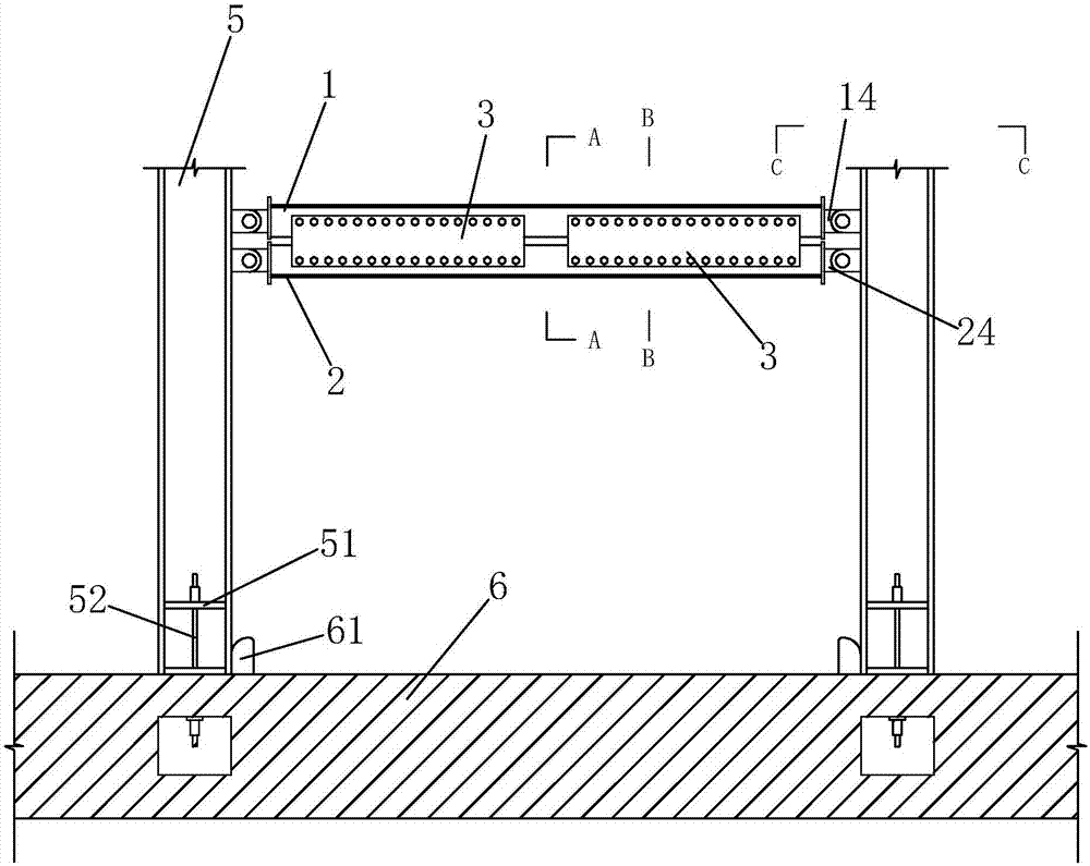
[0033] Such as figure 1 As shown, a frame structure with self-resetting function includes a T-shaped upper bar 1, a T-shaped lower bar 2, two pairs of hard connecting steel plates 3 and two I-shaped columns 5.

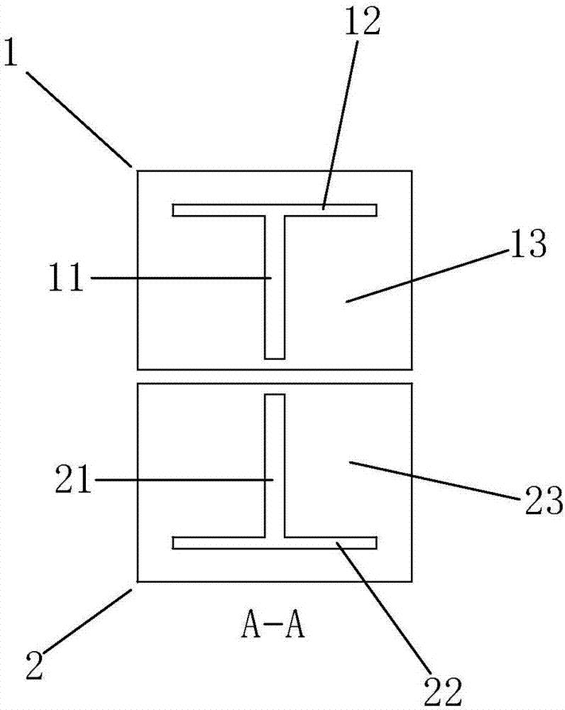
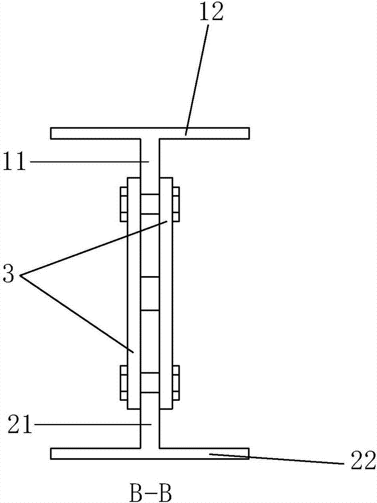
[0034] Such as figure 1 and figure 2 As shown, the T-shaped upper bar 1 includes an upper web 11 and an upper top plate 12 fixedly connected to each other, and an upper end plate 13 is respectively fixed at both ends, and an upper ear plate 14 protrudes from the upper end plate 13, as Figure 5 As shown, in addition, the upper web 11 of the T-shaped upper rod 1 is provided with two elongated through holes 15 parallel to the length direction of the T-shaped upper rod 1 and arranged in sequence along the length direction of the T-shaped upper rod 1;

[0035] Such as figure 1 and figure 2 As shown, the T-shaped lower rod 2 includes a lower web 21 and a lower bottom plate 22 fixedly connected to each other, and the lower end plates 23 are respectively fixed at both e...

Embodiment 2

[0041] Such as Figure 6 As shown, a frame structure with self-resetting function is arranged between two I-shaped columns 5, including a T-shaped upper rod 1, a T-shaped lower rod 2, two pairs of mild steel plates 4 and two I-shaped columns 5 .

[0042] The T-shaped upper rod 1 includes an upper web 11 and an upper top plate 12 fixedly connected to each other, and an upper end plate 13 is respectively fixed at both ends, and an upper ear plate 14 protrudes from the upper end plate 13;

[0043] The T-shaped lower rod 2 includes a lower web 21 and a lower bottom plate 22 fixedly connected to each other, and a lower end plate 23 is respectively fixed at both ends, and a lower ear plate 24 protrudes from the lower end plate 23;

[0044] Such as Figure 6 and Figure 8As shown, two I-shaped columns 5 are vertically placed on the concrete foundation 6, and a stiffening rib 51 is fixed on both sides of the web of each I-shaped column 5, and each stiffening rib 51 is passed throug...


PUM


Abstract

The invention discloses a frame structure with a self resetting function. The frame structure comprises two I-shaped columns, a T-shaped upper rod, a T-shaped lower rod and at least one energy-consuming connection piece. The two I-shaped columns are vertically placed on a concrete foundation; each stiffened rib plate is connected with the concrete foundation through a prestressed bar; the T-shaped upper rod is hinged to the two I-shaped columns through upper lug plates of upper end plates of the two ends of the T-shaped upper rod; the T-shaped lower rod is hinged to the two I-shaped columns through lower lug plates of lower end plates of the two ends of the T-shaped lower rod; the T-shaped upper rod and the T-shaped lower rod are arranged in up-down parallel in a spaced mode; and an upper web of the T-shaped upper rod and a lower web of the T-shaped lower rod are connected through the at least one energy-consuming connection piece. Compared with a traditional steel frame, the frame structure has the self resetting function.

Description

technical field [0001] The invention belongs to the technical field of building structures, and in particular relates to a frame structure with a self-resetting function. Background technique [0002] The anti-seismic thinking in my country at the present stage is "not damaged by small earthquakes, repairable by moderate earthquakes, and not collapsed by major earthquakes". This anti-seismic idea requires that the main structure should not be damaged and can be repaired after the structure encounters an earthquake with fortification intensity. However, due to the uncertainty and complexity of the seismic action, the structure may suffer from an earthquake with a greater intensity than the fortification, which will seriously damage the structural components. In addition, although the structure may not collapse after being subjected to an earthquake of fortification intensity, some components cannot be repaired due to excessive residual deformation. In the end, the entire str...

Claims


Application Information

Patent Timeline
Patent Type & Authority Applications(China)
IPC IPC(8): E04B1/344E04B1/98E04C3/08E04H9/02
CPCE04B1/3441E04C3/083E04H9/023E04H9/024
Inventor 胡红松郭子雄江云帆侯炜
Owner HUAQIAO UNIVERSITY
Why Eureka
Try Eureka