Composite shear wall embedded with fiber-reinforced plastic (FRP) tubes

A composite material pipe and combined shear wall technology, which is applied to walls, building components, buildings, etc., can solve problems such as no self-resetting function, structural damage, and large steel consumption, so as to avoid insufficient self-resetting function and improve deformation Capacity and ductility, effect of section size reduction

Inactive Publication Date: 2016-06-01
GUANGDONG UNIV OF TECH
View PDF12 Cites 3 Cited by
  • Summary
  • Abstract
  • Description
  • Claims
  • Application Information

AI Technical Summary

Problems solved by technology

The above-mentioned patent utilizes that the steel pipe confined concrete has good deformation ability and extension, and placing it at the end of the wall where the force is greater can increase the deformation ability and extension of the wall; however, due to the self-resetting of the whole steel pipe concrete after the steel pipe yields The function (self-centering) is weak, and the structure may still suffer irreparable damage after a major earthquake
For this reason, Chinese Patent Publication No. CN102127941B and CN104088378B invention patents propose to use steel pipe concrete at the end of the wall, and set steel plates on the wall to further increase the ductility and deformation capacity of the wall. In addition to the disadvantages of CN100434601C, there is also the problem of large amount of steel used. Other shear walls utilizing concrete filled steel tubes (such as Chinese Patent Publication Nos. CN202380606U, CN104818784A, CN202380574U, CN203808295U, etc.) also have similar disadvantages (that is, no self-resetting function)
The utility model patent with the Chinese patent publication number CN201459963U proposes to configure all or part of the edge members and the wall with high-strength steel bars and fiber-reinforced composite material bars to make the wall have a self-resetting function during a large earthquake; but this patent does not solve the problem of large deformation. Concrete Cracking in the Tension Area and Concrete Crushing in the Compression Area of ​​the Wall
The utility model patent with the Chinese Patent Publication No. CN201459963U proposes to use concrete filled steel tubes and built-in fiber-reinforced composite material tubes to form composite shear walls in the edge components to increase the mechanical performance and deformation capacity of the structure as a whole, and at the same time make the structure have a certain second-order Rigidity and self-resetting function; however, the application of the above composite shear wall has certain difficulties, mainly in the difficulty of bonding the horizontal steel bars of the wall body to the concrete filled steel tube, which may reduce the overall performance of the composite wall, and at the same time, the FRP pipe and the surrounding concrete are difficult to bond. Collaborative work is also not guaranteed

Method used


Image

  • Composite shear wall embedded with fiber-reinforced plastic (FRP) tubes
  • Composite shear wall embedded with fiber-reinforced plastic (FRP) tubes
  • Composite shear wall embedded with fiber-reinforced plastic (FRP) tubes

Examples


Embodiment 1

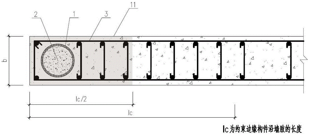
[0052] see Figure 1a In the composite shear wall with built-in fiber-reinforced composite material tubes in this embodiment, a fiber-reinforced composite material tube 1 is arranged in the hidden column at the end 11 of the shear wall, and the tube is filled with concrete 2 to form fiber-reinforced composite material confined concrete. The fiber-reinforced composite material pipe 1 is arranged at the end of the shear wall. The fiber-reinforced composite material pipe 1 is a carbon fiber-reinforced composite material pipe (referred to as CFRP pipe), and the fiber-reinforced composite material pipe 1 may also be a glass fiber-reinforced composite material pipe (referred to as a GFRP pipe), an aramid fiber-reinforced composite material pipe (referred to as a AFRP pipe), basalt fiber pipe (referred to as BFRP pipe). Concrete 2 is one of ordinary concrete, high-strength concrete, expansive concrete, fly ash concrete, lightweight aggregate concrete, recycled aggregate concrete, fib...

Embodiment 2

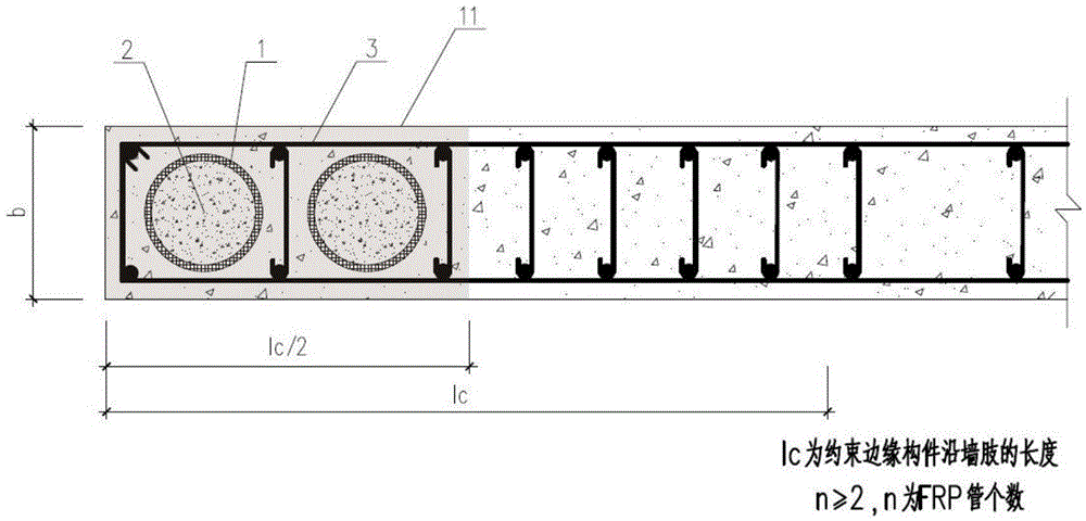
[0055] see Figure 1b The difference between this embodiment and the first embodiment is that two fiber-reinforced composite material tubes 1 are arranged in the hidden column of the shear wall body. Considering the actual load of the shear wall, when the load is large, multiple (number of tubes N>=2) fiber-reinforced composite tubes 1 can be arranged in the concealed column to meet the demand. Wherein the fiber reinforced composite pipe 1 may be Figure 13 Any combination of two or more shapes. Other details are the same as in Embodiment 1.

Embodiment 3

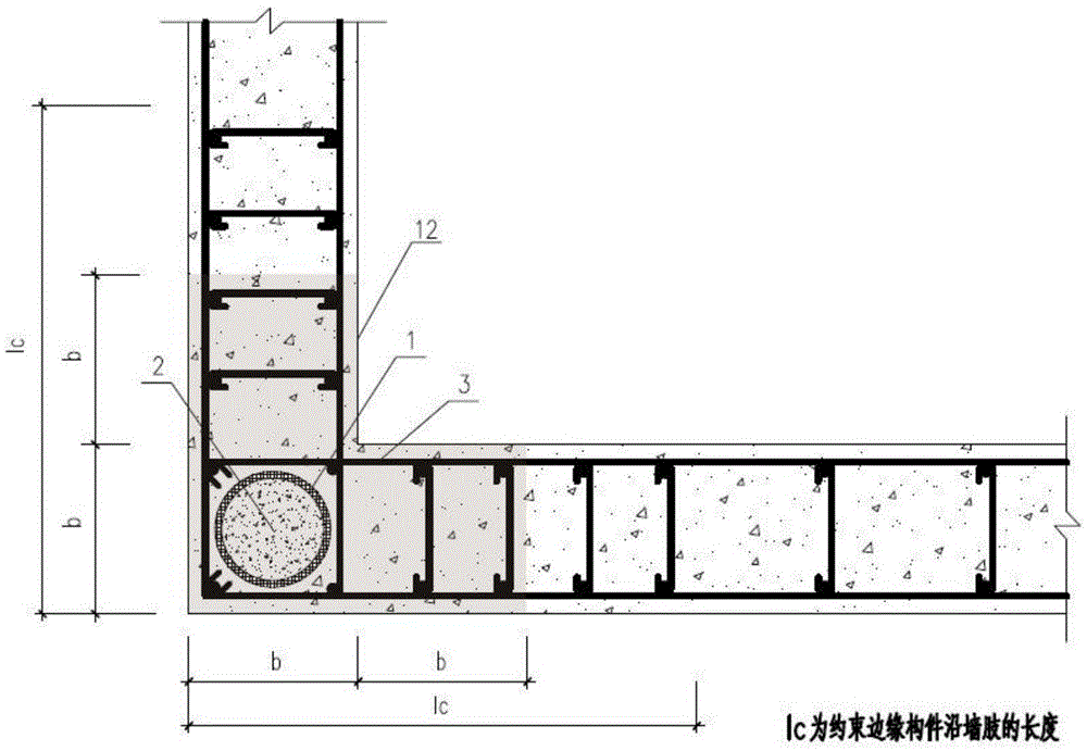
[0057] see Figure 2a The difference between this embodiment and the first embodiment is that a fiber-reinforced composite material tube 1 is arranged in a hidden column at the intersection of two wall limbs of the shear wall at 12 positions, and the fiber-reinforced composite material tube 1 and the concrete 2 filled inside are two The latter replaces the traditional reinforced concrete combination to bear the vertical load from the upper part. Similarly, the horizontal reinforcement in the shear wall can bypass the fiber-reinforced composite material tube 1 for anchoring. Wherein the fiber reinforced composite pipe 1 may be Figure 13 Any combination of two or more shapes. Other details are the same as in Embodiment 1.


PUM


Abstract

The invention discloses a composite shear wall embedded with fiber-reinforced plastic (FRP) tubes. The shear wall is a reinforced concrete shear wall; at least one fiber-reinforced plastic tube is arranged inside the shear wall; concrete is filled into the fiber-reinforced plastic tubes. FRP has high concrete confining strength and high deformability and has the characteristics of remarkable two-order rigidity at the same time, and the FRP tubes are placed at one or more of wall body deformation positions or large-stress positions such as wall ends, intersections between two wall columns and intersections among a plurality of wall columns, so that the composite shear wall has the characteristics of high deformability and prevention of crashing of stressed area concrete, and has remarkable two-order rigidity in order that a wall body has a self-reset function in the case of large deformation, so that the defect of insufficient self-reset function under excessive ductility in the conventional steel tube concrete composite shear wall is effectively overcome.

Description

technical field [0001] The invention belongs to the technical field of reinforced concrete structures, and in particular relates to a composite shear wall with built-in fiber-reinforced composite material tubes. Background technique [0002] Reinforced concrete shear wall is a lateral force-resisting member widely used in modern high-rise and super high-rise building structures. Meet the structural design requirements. Reinforced concrete shear walls are generally composed of wall body and edge members. According to the needs of different seismic levels, the edge members can be designed as structural edge members or constrained edge members. Generally, the ductility and bearing capacity of the constrained edge members are increased by increasing the vertical stress bars and stirrups of the edge members, thereby increasing the overall bearing capacity and deformation capacity of the reinforced concrete wall. [0003] In ordinary reinforced concrete shear walls, due to the ...

Claims


Application Information

Patent Timeline
Patent Type & Authority Applications(China)
IPC IPC(8): E04B2/68
CPCE04B2/68
Inventor 陈光明林楚君张文鹏
Owner GUANGDONG UNIV OF TECH
Why Eureka
Try Eureka