
Parking device and parking garage

A parking device and vehicle technology, applied in the field of parking devices and parking garages, can solve the problems of insufficient parking space, tight parking spaces, high parking costs, etc., and achieve the effect of simple and convenient transfer

Pending Publication Date: 2017-06-30
陆建雄
View PDF0 Cites 2 Cited by
  • Summary
  • Abstract
  • Description
  • Claims
  • Application Information

AI Technical Summary

Problems solved by technology

[0005] One of the objects of the present invention is to provide a parking device, which aims to solve the problem of tight parking spaces and insufficient parking space in the prior art;
[0006] Another object of the present invention is to provide a parking garage, which aims to solve the problems of high parking costs and low efficiency in the prior art

Method used


Image

  • Parking device and parking garage
  • Parking device and parking garage
  • Parking device and parking garage

Examples


no. 1 example

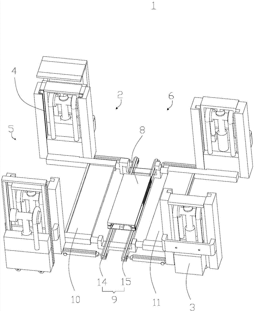
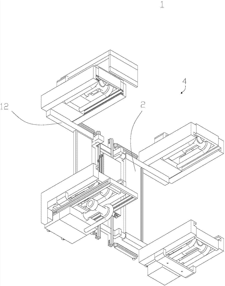
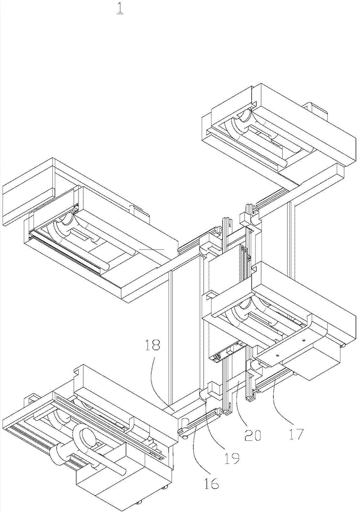
[0044] Please refer to figure 1 , figure 2 as well as image 3 , with reference to Figure 4 , the present embodiment provides a parking device 1, which is mainly used in enterprises or communities with large traffic volume, tight parking spaces and insufficient space, so as to realize parking anytime and anywhere.

[0045] The parking device 1 includes a support mechanism 2, a control mechanism 3, a drive mechanism 4, a connecting mechanism 5, and a vehicle lifting and pushing cart 6. The side ends are respectively connected with the first support assembly 10 and the second support assembly 11 , and the lower end of the drive mechanism 4 is connected with the support mechanism 2 through the connection mechanism 5 .

[0046] Please refer to figure 1 , Figure 5 as well as Figure 6 , the vehicle lifting push car 6 includes a lifting mechanism 7, a positioning plate 8 and a translation track 9, the positioning plate 8 is connected with the upper surface of the lifting me...

no. 2 example

[0061] Please refer to Figure 10 , this embodiment provides a parking garage 43, which includes a parking garage body 44 and the parking device 1 in the first embodiment, and the parking device 1 is installed inside the parking garage body 44.

[0062]In summary, the parking garage 43 includes the above-mentioned parking device 1 , and the parking device 1 has a supporting mechanism 2 , a control mechanism 3 , a driving mechanism 4 , a connecting mechanism 5 and a vehicle lifting and pushing cart 6 . Wherein, the vehicle lifting and pushing cart 6 has a lifting mechanism 7 and a translation track 9, and the translation track 9 is used to place the vehicle to be parked on the support mechanism 2, and the lifting mechanism 7 is used to drive the positioning plate 8 and the translation track 9 Ascending or descending, the structure can therefore easily and conveniently transfer vehicles that need to be parked. Simultaneously, because the two ends of the first slide rail 14 are ...


PUM


Abstract

The invention provides a parking device and a parking garage and belongs to the field of vehicle engineering machinery. The parking device comprises a supporting mechanism, a control mechanism, a driving mechanism, a connecting mechanism and a vehicle lifting pushing vehicle. The vehicle lifting pushing vehicle comprises a lifting mechanism, a positioning plate and a translation track. The positioning plate is connected with the upper surface of the lifting mechanism. The bottom of the lifting mechanism is slidably connected with the translation track. The supporting mechanism comprises a first supporting assembly and a second supporting assembly. The connecting mechanism comprises four or more connecting arms. The two side ends of the translation track are fixedly connected with the first supporting assembly and the second supporting assembly through one ends of the connecting arms. The driving mechanism comprises four or more stretching mechanisms connected with the other ends of the connecting arms. The control mechanism is fixedly connected with the stretching mechanism. The tensioning mechanism drives the vehicle lifting pushing vehicle to rise or fall through the control mechanism. The parking garage is provided with the parking device, so that the problems of low parking efficiency and high cost in traditional parking are greatly solved.

Description

technical field [0001] The invention relates to the field of vehicle engineering machinery, in particular to a parking device and a parking garage. Background technique [0002] With the rapid development of China's economy, automobiles have increasingly become an indispensable means of transportation in people's daily life, and practical problems such as parking difficulties and high parking garage fees have also followed. [0003] At present, most of the smart parking garages in enterprises and communities adopt the method of manual parking and then raising the mechanical structure to realize the parking of cars in the air. Although this method improves the utilization rate of space and reduces the floor area of ​​the parking garage, However, the operation and maintenance cost of the parking garage in the later period limits the popularization and use of this kind of smart parking garage. In addition, since the process of parking and picking up the car is concentrated in ...

Claims


Application Information

Patent Timeline
IPC IPC(8): E04H6/22
CPCE04H6/22
Inventor 陆建雄刘浩
Owner 陆建雄
Learn More