Multi-target optical tracking method

An optical tracking, multi-target technology, applied in image data processing, measuring devices, instruments, etc., can solve the problem of refresh rate drop, etc., to achieve the effect of not dropping the refresh rate

Active Publication Date: 2017-06-30
BEIJING INSTITUTE OF TECHNOLOGYGY
View PDF6 Cites 12 Cited by
  • Summary
  • Abstract
  • Description
  • Claims
  • Application Information

AI Technical Summary

Problems solved by technology

This results in the system's refresh rate dropping exponentially when multiple emitters are used in cascade
Since the larger the tracking area, the more transmitters are needed

Method used


Image

  • Multi-target optical tracking method
  • Multi-target optical tracking method
  • Multi-target optical tracking method

Examples


Embodiment Construction

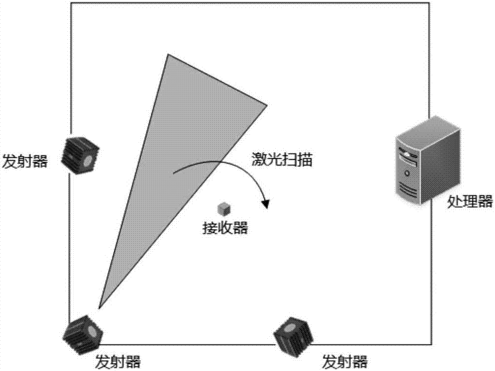
[0048] The present invention will be described in detail below in combination with a specific implementation manner in which the number of transmitters is m=3.

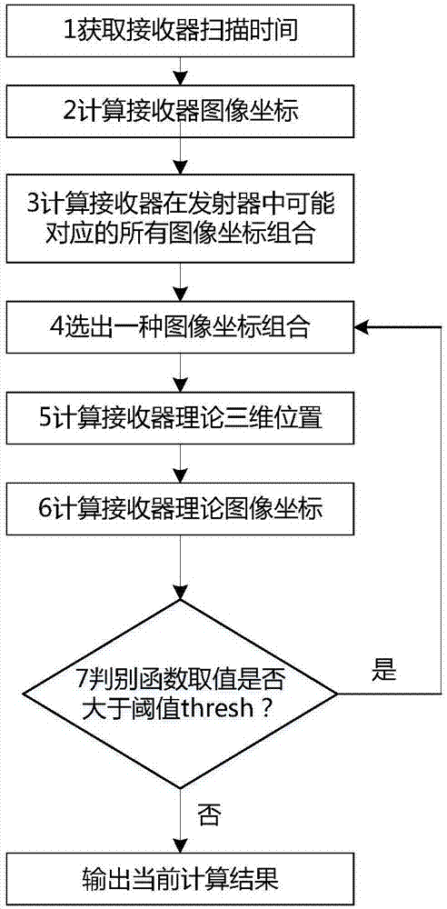
[0049] Such as figure 1 As shown, it is a flow chart of the implementation method of the present invention; specifically, a multi-target optical tracking method includes the following steps:

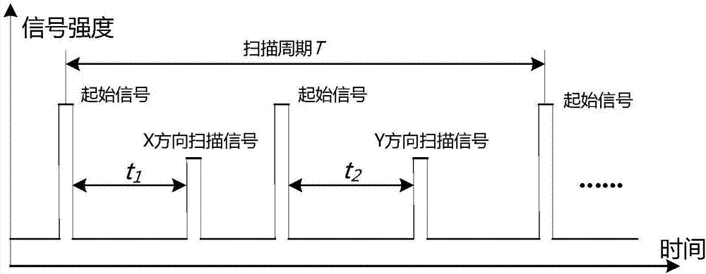
[0050] Step 1: The receiver records the time difference between the scanning signal and the start signal sent by each transmitter in the horizontal X direction, and the time difference between the scan signal and the start signal sent by each transmitter in the vertical Y direction;

[0051] Step 2: Compute all image coordinates u of the receiver relative to the 3 transmitters using the time difference from step 1 i and v i , where u i is the image coordinate of the receiver in the horizontal X direction relative to the i-th transmitter, v i is the image coordinate of the receiver in the vertical Y direction relative to the...


PUM


Abstract

The invention provides a high-precision and low-cost optical tracking method, which utilizes a receiver to calculate the time to receive a scanning signal so as to obtain the image coordinate of the receiver in the emitters; verifying all possible image coordinate corresponding relationships to find the only one correct corresponding relationship between the image coordinate of the receiver to the emitters; and then realizing the solution to the spatial coordinate of the receiver. From the technical principles, the method solves the problem with the decrease in the data refresh rate when plural emitters are used by cascading and using emitters in any number without reducing the tracking data refresh rate.

Description

technical field [0001] The invention belongs to the field of tracking and positioning, in particular to a multi-target optical tracking method. Background technique [0002] In today's tracking and positioning field, Vicon and HTC VIVE are relatively commonly used technologies. Vicon uses a high-frame-rate, high-resolution camera as a signal capture device, and an infrared reflective ball as a tracked marker. If the reflective ball is captured by multiple cameras, its spatial position can be calculated by computer vision. The tracking accuracy and refresh rate of the Vicon system are related to the performance of the tracking camera used, for example, its V16 camera has a resolution of 16 million pixels and a frame rate of 120Hz. Due to the great difficulty in manufacturing high-performance cameras and the need for subsequent data processing equipment, this leads to high costs for the Vicon system, which can only be used in professional fields and cannot be widely populariz...

Claims


Application Information

Patent Timeline
IPC IPC(8): G01S5/16G06T7/20
CPCG01S5/16G06T7/20
Inventor 翁冬冬李冬杨奕
Owner BEIJING INSTITUTE OF TECHNOLOGYGY
Why Eureka
Try Eureka