Circuit design for pipe network water pressure monitoring

A technology for monitoring circuits and water pressure, applied to electrical components, piping systems, mechanical equipment, etc., can solve the problems of large distribution area of ​​pipeline network and inconvenient maintenance of pipeline network

Pending Publication Date: 2021-03-23
JIUJIANG PRECISION MEASURING TECH RES INST
View PDF0 Cites 0 Cited by
  • Summary
  • Abstract
  • Description
  • Claims
  • Application Information

AI Technical Summary

Problems solved by technology

At present, the water pressure gauge is basically realized by manual reading, because of the oil pollution of the water pressure gauge, the large number of pressure gauges in th

Method used


Image

  • Circuit design for pipe network water pressure monitoring
  • Circuit design for pipe network water pressure monitoring
  • Circuit design for pipe network water pressure monitoring

Examples


Embodiment Construction

[0015] Through the following description of the embodiments, it will be more helpful for the public to understand the present invention, but the specific embodiments given by the applicant cannot and should not be regarded as limitations on the technical solutions of the present invention, any components or technical features Changes to the definition and / or formal but not substantive changes to the overall structure should be regarded as the scope of protection defined by the technical solutions of the present invention.

[0016] Example:

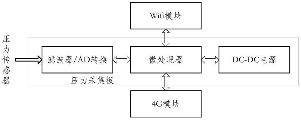
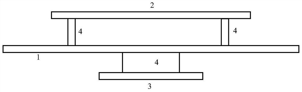
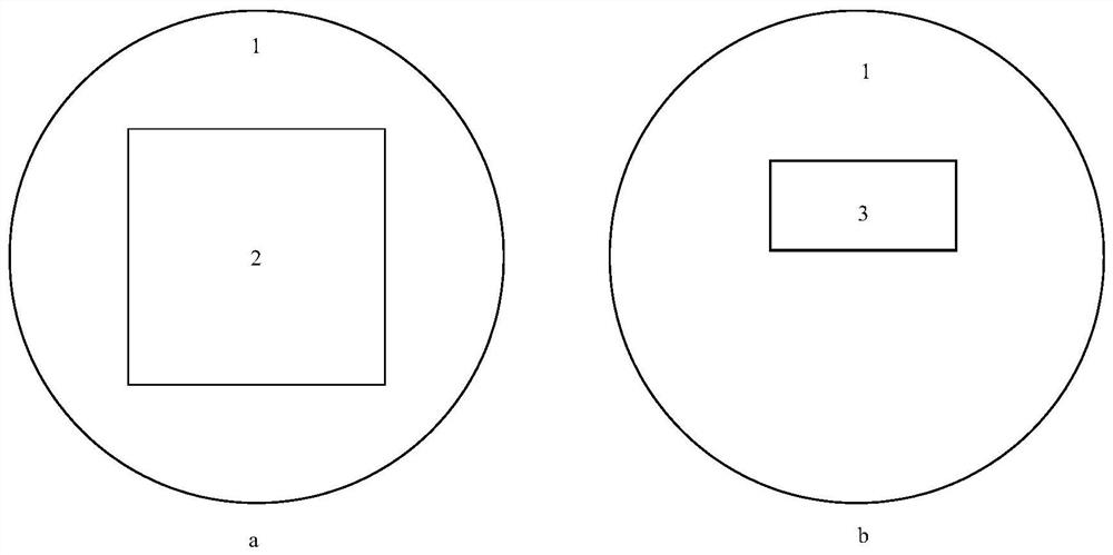
[0017] Such as Figure 1-Figure 3 The design of a pipe network water pressure monitoring circuit shown includes a pressure acquisition board 1, a 4G data transmission module 2, a serial port to WiFi module 3, and a needle header 4.

[0018] First, the water pressure monitoring circuit of the pipe network is mainly composed of three parts, among which the 4G data transmission module 3 and the serial port to WiFi module 3 are inserted into ...


PUM


Abstract

The invention discloses circuit design for pipe network water pressure monitoring. The circuit design comprises a pressure acquisition board, a 4G data transmission module, a serial port to WiFi module, a needle base and the like, and is characterized in that a combined structure that different modules are selectively installed through the needle base is adopted, and part or all functions can be flexibly configured or selected for use. The overall design is simple, use under different conditions is flexible and convenient, and the defects in the prior art are overcome.

Description

technical field [0001] The invention relates to the field of fire-fighting equipment status monitoring, in particular to a design of a pipe network water pressure monitoring circuit. Background technique [0002] The water pressure gauge is an important and widely used equipment in the construction of urban water supply pipe network. At present, with the development of the city, the pipe network becomes more and more complex with the development of building scope, height and structure. At present, the water pressure gauge is basically realized by manual reading. Because of the oil pollution of the water pressure gauge, the large number of pressure gauges in the building, or the large distribution area of ​​the pipeline network, it is inconvenient for daily residents to manage water use or maintain the pipeline network. [0003] The invention adopts various interface forms such as wireless network transmission module and 4G data transmission module to realize data transmissio...

Claims


Application Information

Patent Timeline
IPC IPC(8): H04L29/08G08C17/02F17D3/01
CPCH04L67/025H04L67/12G08C17/02F17D3/01
Inventor 蒋礼威周丰镭苏长青简丹
Owner JIUJIANG PRECISION MEASURING TECH RES INST
Why Eureka
Try Eureka